00197783-01_AI_Gantry-Retrofit_X-Series_S_INTERNAL_de_en.pdf - 第78页
Anhang Platinenbeschreibungen 4.2.2 Vision Board Spread Spectrum HCU [0 3067289-xx] 78 Gantry Retrofit Portalna chrüstung 4.2.2.1 4 . 2 . 2 . 1 D I P - S c h a lt e r a m V is io n - B o a r d ( D ig it a l- V e r s io n…
Anhang
4.2.2 Vision Board Spread Spectrum HCU [03067289-xx] Platinenbeschreibungen
Gantry Retrofit Portalnachrüstung 77
4.2.2
4.2.2 Vision Board Spread Spectrum HCU [03067289-xx]
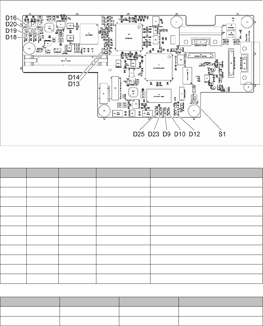
Vision Board Spread Spectrum HCU [03067289-xx]
03067289-02
LED [03067289-02]
DIP-Schalter S1 [03067289-02]
LED Farbe Status Signalname Beschreibung
D9 GN ON LED_XC_OK RUN
D10 RD ON LED_XC_ERR ERROR
D12 RD ON XC_RESET RESET
D13 GN ON IO/LVDS51P LP-Kamera aktiv
D14 GN ON IO/LVDS51N BE-Kamera aktiv
D16 GN ON P12VCAM_I +12VDC für Kamera
D18 GN ON P5VCAM +5VDC für Kamera
D19 GN ON P2.5VCAM + 2.5 VDC für Kamera
D20 GN ON P3.3VCAM + 3.3VDC für Kamera
D23 GN ON P5V +5VDC
D25 GN ON P15V +15VDC
Schalter Status Signalname Beschreibung
S1.1 OFF HW_RESET ON: RESET CAN-Controller
S1.2 OFF CAN_ID Nicht benutzt

Anhang
Platinenbeschreibungen 4.2.2 Vision Board Spread Spectrum HCU [03067289-xx]
78 Gantry Retrofit Portalnachrüstung
4.2.2.1
4.2.2.1 DIP-Schalter am Vision-Board (Digital-Version02)
DIP-Schalter am Vision-Board (Digital-Version 02)
* Je nach Maschinentyp sind nicht alle Portale verfügbar.
S Portal* Anmerkung
1 2 3 4
1 OFF OFF OFF OFF Reset - CAN-Prozessor
2 OFF ON OFF ON PID0 Adress-Schalter 1 -> Por-
tal
3OFF OFF ON ONPID1 Adress Schalter 2 -> Por-
tal
4 OFF OFF OFF OFF CAN R - Schalter für den
Abschlusswiderstand am CAN-
Bus
5ON ON ON ONSpeed: ON = 1 Mbit/s, OFF =
500 Kbit/s
6ON ON ON ONCAN ID - für X-Maschine ON
Anhang
4.2.3 Kopfinterface C700X-L/R HR Platinenbeschreibungen
Gantry Retrofit Portalnachrüstung 79
4.2.3
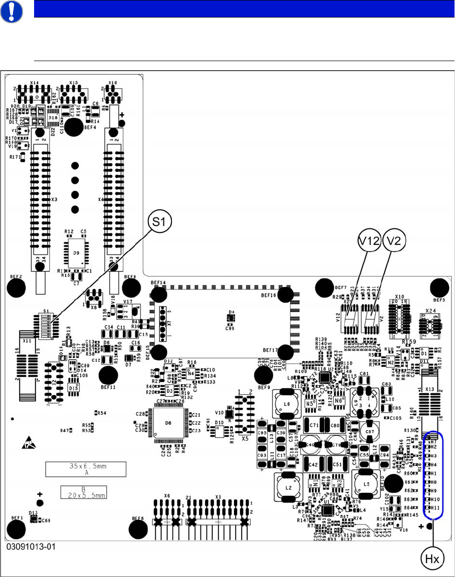
4.2.3 Kopfinterface C700X-L/R HR
Kopfinterface C700X-L/R HR
Es gibt zwei Bauformen für das Kopfinterface. Je nach Portal wird das Kopfinterface C700X-L oder
C700X-R verwendet.
Standardportal (nicht gedreht) [03091013-01]
HINWEIS
C&P20 P
Wird auf einen C&P20 P umgerüstet, dann muss das Kopfinterface mindestens Funktionsstand
-03 haben.