00197783-01_AI_Gantry-Retrofit_X-Series_S_INTERNAL_de_en.pdf - 第106页
Installation Gantry 1/3: Removing the Y Trai ling Cable and Trailing Interfac e 3.1.4 Removing the Top Cover 106 Gantry Retrofit Portalna chrüstung 3.2 3 . 2 G a n t r y 1 / 3 : R e m o v in g t h e Y T r a ilin g C a b …
Installation
3.1.4 Removing the Top Cover Preparatory Steps
Gantry Retrofit Portalnachrüstung 105
3.1.4
3.1.4 Removing the Top Cover
Removing the Top Cover
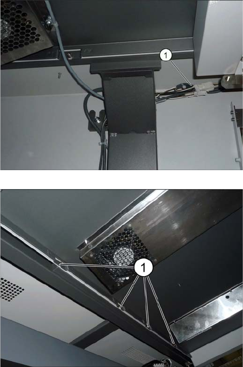
For better access to the work area, we recommend that you remove the top cover on the placement area.
► Unplug the connector (1) on the cover fan at both
sides.
► Loosen the eight screws fastening the cover (four on
each side) (1).
► Lift the cover up and off the machine.
Installation
Gantry 1/3: Removing the Y Trailing Cable and Trailing Interface 3.1.4 Removing the Top Cover
106 Gantry Retrofit Portalnachrüstung
3.2
3.2 Gantry 1/3: Removing the Y Trailing Cable and Trailing Interface
Gantry 1/3: Removing the Y Trailing Cable and Trailing Interface
NOTICE
Gantry 1 or 3
If a gantry is retrofitted in a placement area (PA), you will need to replace the long trailing cable
for the gantry already fitted with the shorter version. The trailing interface must also be moved.
This procedure is exactly the same for both PA1 and PA2.
NOTICE
Service manual
► Observe the relevant chapter in the service manual.
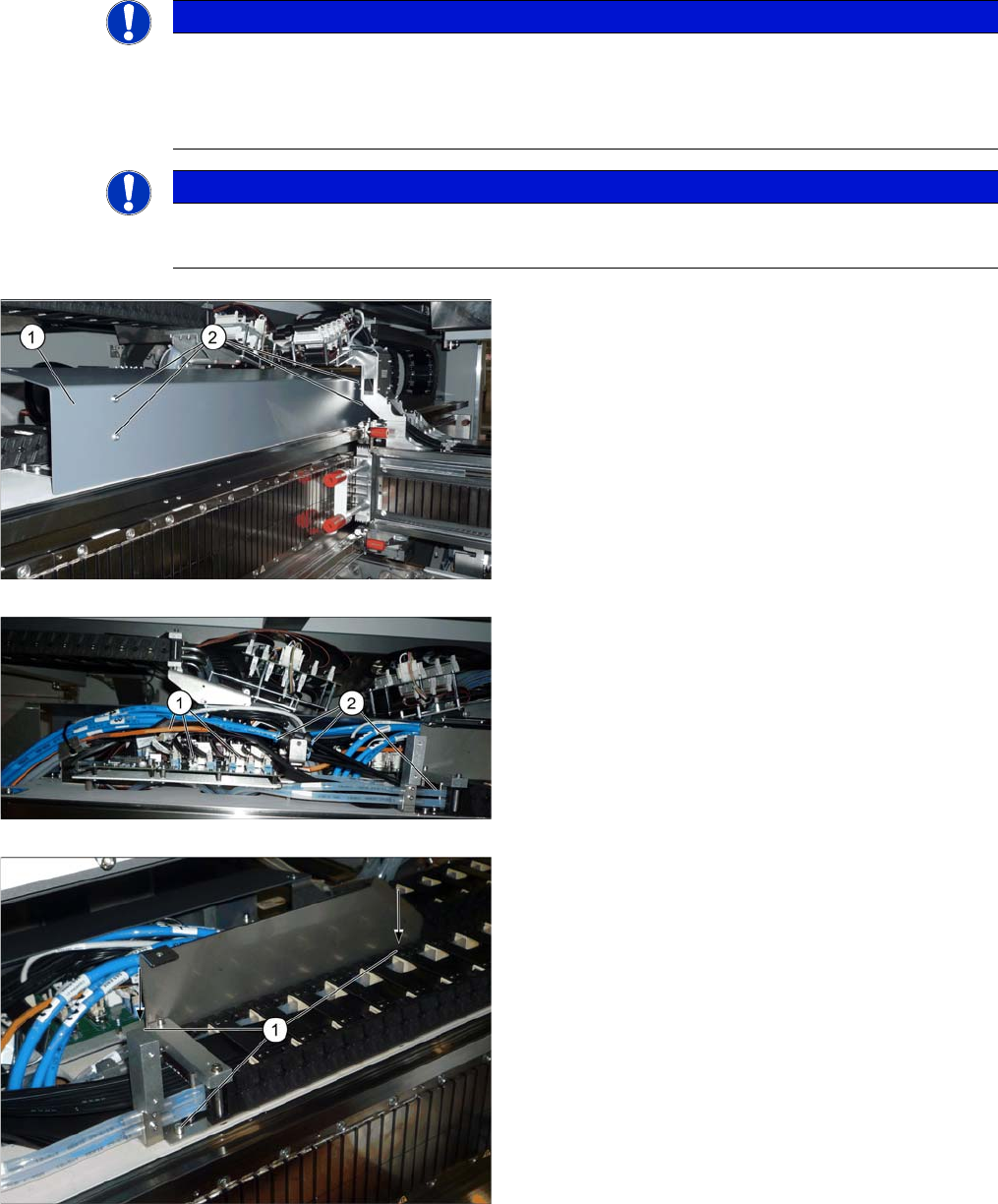
► Remove the screws (2) and dismantle the covers (1)
on the trailing interface boards in both placement ar-
eas.
► Unplug all pneumatic connections (blue, black and
white hoses) (2).
► Unplug all electrical connections (1) on the trailing in-
terface and Vision Hotlinik Adapter.
► Remove the long screw (3) with the Y pieces.
► Use a cable tie to bind all cables and hoses together.
► Loosen the three screws (1) fastening the bottom
holder on the Y trailing cable.
⇨ The lower end of the Y trailing cable has now been
completely disconnected from the machine.
Installation
3.1.4 Removing the Top Cover Gantry 1/3: Removing the Y Trailing Cable and Trailing Interface
Gantry Retrofit Portalnachrüstung 107
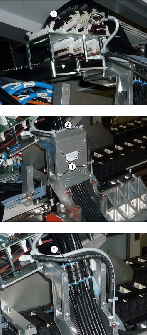
► Unplug all electrical connections (1) from the top of
the Y gantry interface.
► Loosen the six screws (1) fastening the cover on the
hose couplings.
► Remove the two cable ties (2).
► Unplug all pneumatic connections (1).
► Disconnect the cooling air tubes from the Y motor.
► Pull the cooling air hoses back through the goose-
neck (Y trailing cable holder).