00197783-01_AI_Gantry-Retrofit_X-Series_S_INTERNAL_de_en.pdf - 第125页
Installation 3.1.4 Removing the Top Cover Fitting the Y Trailing Cable for th e New Gantry 2 /4 Gantry Retrofit Portalnachrüstung 125 ► Fasten the Y gantry interfa ce with four screws 3x6 and two bolts (1) . Secure the b…
Installation
Fitting the Y Trailing Cable for the New Gantry 2/4 3.1.4 Removing the Top Cover
124 Gantry Retrofit Portalnachrüstung
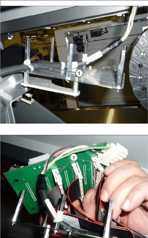
► Fasten the Y motor cable (connector X4*b)
[03095097-xx] with cable ties (1) to the white sleeves.
► Connect the cables (1) to the underside of the Y gan-
try interface.
► Position the Y gantry interface on the six bolts.
Installation
3.1.4 Removing the Top Cover Fitting the Y Trailing Cable for the New Gantry 2/4
Gantry Retrofit Portalnachrüstung 125
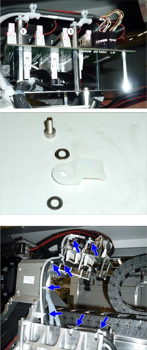
► Fasten the Y gantry interface with four screws 3x6
and two bolts (1). Secure the bolts with Loctite 241.
► Fit a cable duct to each of the bolts.
Order: washer + cable duct + washer + screw
Secure the screws with Loctite 241.
► Connect all flat ribbon cables to the top side of the Y
gantry interface.
► Connect all remaining cables to the Y gantry interface
and fasten these with cable ties, as shown.
► Tighten all cable ties.
Installation
Fitting the Y Trailing Cable for the New Gantry 2/4 3.1.4 Removing the Top Cover
126 Gantry Retrofit Portalnachrüstung
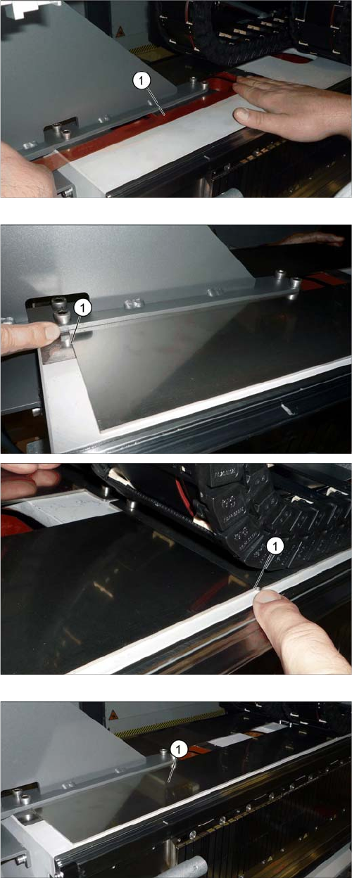
► Attach a strip of double-sided adhesive tape (1) to the
unwind surface of the trailing cable, as shown.
► Pull off the upper protective foil on the adhesive strip.
► Pull the protective foil off the "trailing cable support
plate 2P assy" and attach this to the roll-off area of
the trailing cable.
Make sure that the unwind plate is exactly parallel at
the front and back (1).
The diagram shows the completely attached "trailing ca-
ble support plate 2P assy" (1).