00197783-01_AI_Gantry-Retrofit_X-Series_S_INTERNAL_de_en.pdf - 第116页
Installation Fitting the Trailing Interface Boar ds 3.1.4 Removing the Top Cove r 116 Gantry Retrofit Portalna chrüstung The installation of the trailing interface an d Vision Hotlink A dpater b oard, plus the pneum atic…
Installation
3.1.4 Removing the Top Cover Fitting the Trailing Interface Boards
Gantry Retrofit Portalnachrüstung 115
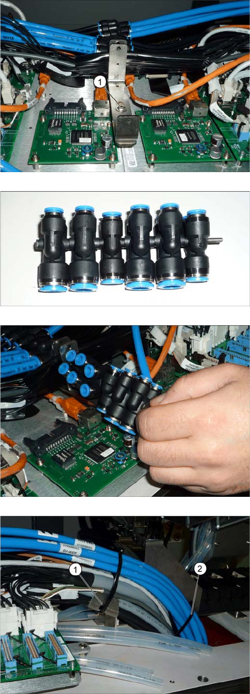
► Fasten the shaft holder with a screw (1) to the middle
bolt.
► Prepare the six Y pneumatic couplings in the order
10-10-8-10-10-8.
► Fit the Y pneumatic couplings between the boards.
► Perform the following steps on both sides of the
placement area.
► Fasten all cables (but no hoses yet) to the holder,
with a cable tie (1).
► Fasten all hoses with another cable tie (2) within the
area of the I beam (just under the upper edge). Do not
overtighten, to avoid pinching the hoses.
► Fasten the hoses with another cable tie.
Installation
Fitting the Trailing Interface Boards 3.1.4 Removing the Top Cover
116 Gantry Retrofit Portalnachrüstung
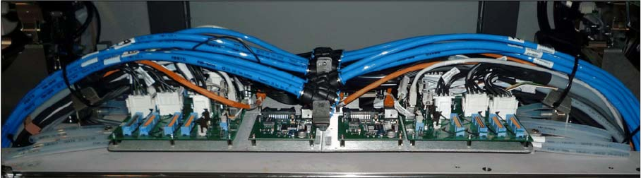
The installation of the trailing interface and Vision Hotlink Adpater board, plus the pneumatic hoses, at
the machine end, has now been completed.
Trailing interface and Vision Hotlink Adapter fully installed
Installation
3.1.4 Removing the Top Cover Fitting the Gantry
Gantry Retrofit Portalnachrüstung 117
3.5
3.5 Fitting the Gantry
Fitting the Gantry
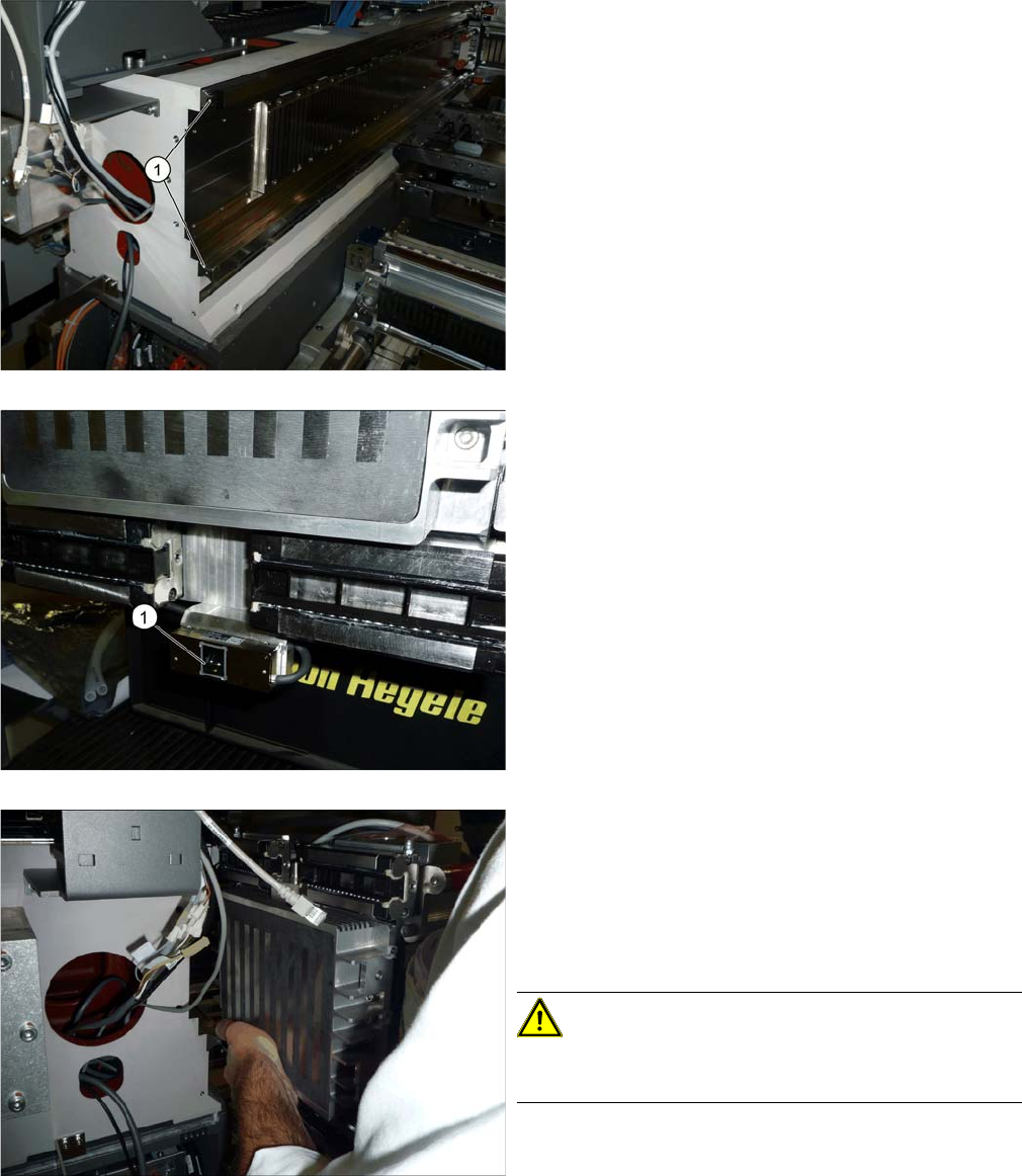
► Remove the buffer holder and the plastic covers (1)
on both rails.
► Loosen the 16 screws fastening the four trolleys to
the gantry. The four trolleys must then have room for
movement.
► Remove the protective foil (1) on the incremental en-
coder on the gantry.
When installing the gantry, you either need a gantry lift or
the help of a second person.
► Lift the gantry onto the guide rails.
► Position the gantry as exactly as possible and then
push it carefully onto the rails. This presses the plas-
tic sleeves in the trolley bearing out.
CAUTION!
Do not pull the gantry backwards. This could cause balls
to fall out of the trolley bearings.