00197783-01_AI_Gantry-Retrofit_X-Series_S_INTERNAL_de_en.pdf - 第115页
Installation 3.1.4 Removing the Top Cover Fitting the Trailing Interface Boards Gantry Retrofit Portalnachrüstung 115 ► Fasten the shaft holder with a screw (1) to the middle bolt. ► Prepare the six Y pneumatic couplings…
Installation
Fitting the Trailing Interface Boards 3.1.4 Removing the Top Cover
114 Gantry Retrofit Portalnachrüstung
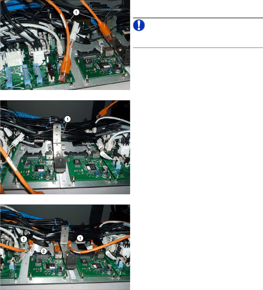
► First, establish all connections to the trailing interface,
at the machine end.
NOTICE!
We recommend that you connect the orange hotlink
cable (1) later on.
► Bind together all cables running through the middle
[03076516-xx (with X13ba and X14ba) and
[03076477-xx] (voltage for Vision Hotlink Adapter)
with a zipper hose (1) and stow these away between
the two vertical holders.
► Connect the hotlink cables (1) and (2) and fasten this
with cable ties to the cable harness holder.
Installation
3.1.4 Removing the Top Cover Fitting the Trailing Interface Boards
Gantry Retrofit Portalnachrüstung 115
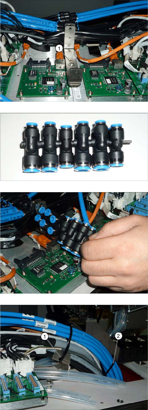
► Fasten the shaft holder with a screw (1) to the middle
bolt.
► Prepare the six Y pneumatic couplings in the order
10-10-8-10-10-8.
► Fit the Y pneumatic couplings between the boards.
► Perform the following steps on both sides of the
placement area.
► Fasten all cables (but no hoses yet) to the holder,
with a cable tie (1).
► Fasten all hoses with another cable tie (2) within the
area of the I beam (just under the upper edge). Do not
overtighten, to avoid pinching the hoses.
► Fasten the hoses with another cable tie.
Installation
Fitting the Trailing Interface Boards 3.1.4 Removing the Top Cover
116 Gantry Retrofit Portalnachrüstung
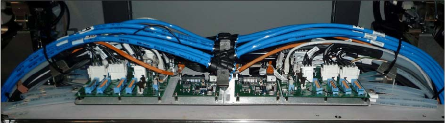
The installation of the trailing interface and Vision Hotlink Adpater board, plus the pneumatic hoses, at
the machine end, has now been completed.
Trailing interface and Vision Hotlink Adapter fully installed