00197783-01_AI_Gantry-Retrofit_X-Series_S_INTERNAL_de_en.pdf - 第136页
Appendix Excerpts from the Service Manual 4.1.1 Replacing the Trailing Cable 136 Gantry Retrofit Portalna chrüstung The trailing cable now lie s loose in the machine. ► Carefully remove t he trailing cable from the machi…
Appendix
4.1.1 Replacing the Trailing Cable Excerpts from the Service Manual
Gantry Retrofit Portalnachrüstung 135
Disconnecting the Trailing Cable on the Gantry Side
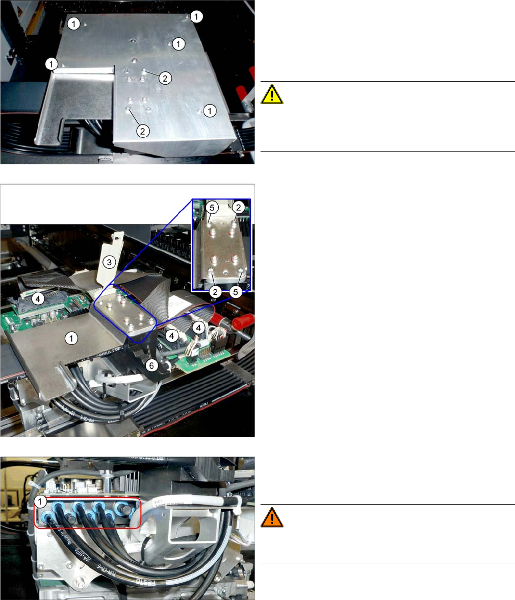
X34iS – G antry – 2 Dismantl ing the Bo ard Cover
1. Fastening screws 5x (not sealed)
2. Fastening screws 2x (with sealing varnish)
► Dismantle the board cover. You need to loosen the
fastening screws for this at(1) and (2).
CAUTION!
To avoid short circuits, only dismantle the cover when the
machine is switched off!
► Loosen the two screws (2) fastening the downholder
(1) and then remove the downholder.
► Loosen the cable clamp (3).
► Unplug the connectors (4). You may want to mark
their positions, to make clear assignment easier later
on.
► Loosen the two screws (5) fastening the trailing cable
clamp (6).
► Pull the hoses off the gantry distributor. You may
want to mark their positions, to make clear assign-
ment easier later on.
WARNING!
Risk of injury to hands
Use the "hose unlocking tool" for this [03047090-xx].
Appendix
Excerpts from the Service Manual 4.1.1 Replacing the Trailing Cable
136 Gantry Retrofit Portalnachrüstung
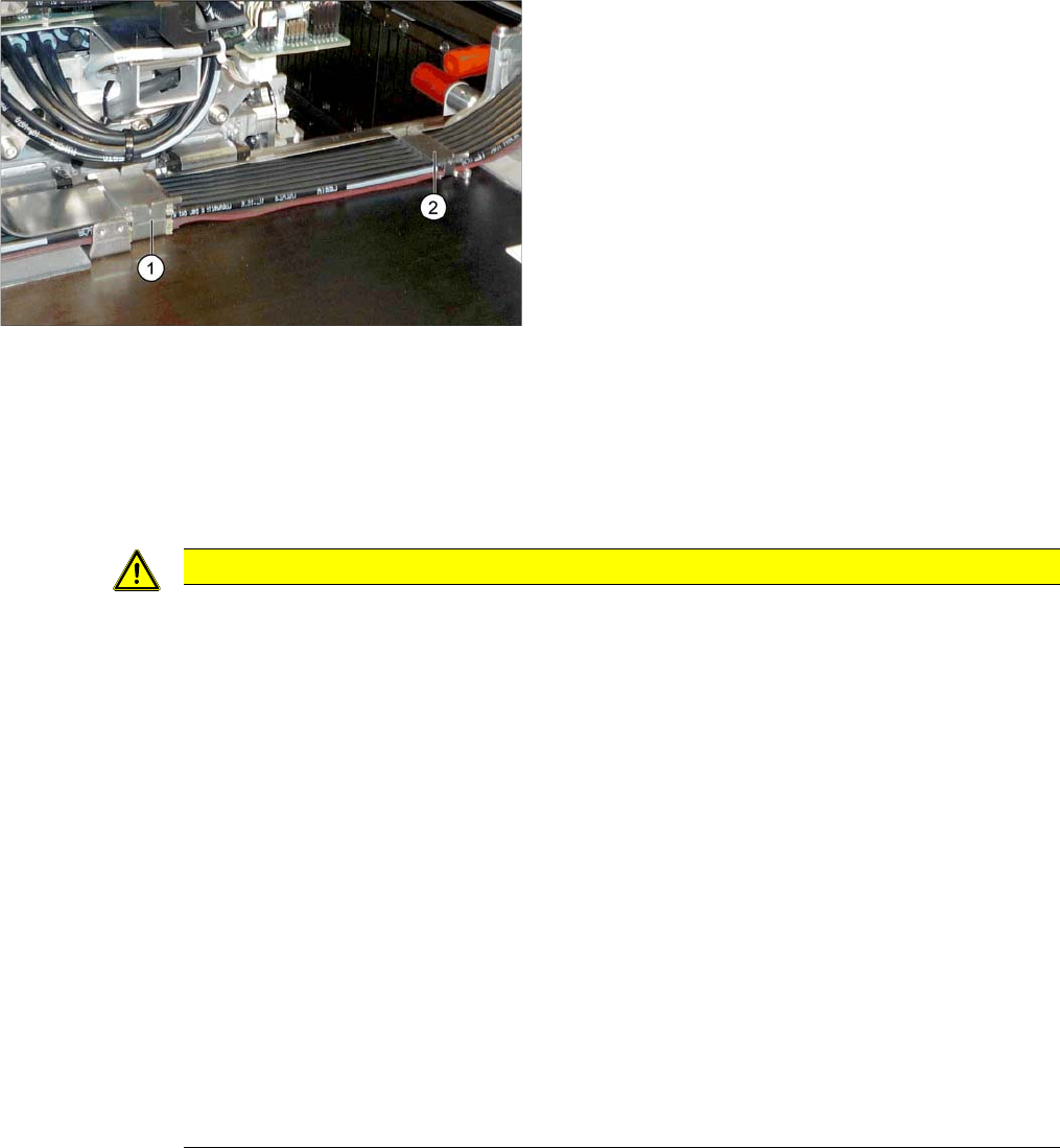
The trailing cable now lies loose in the machine.
► Carefully remove the trailing cable from the machine.
Installation
► Installation is performed by following the above instructions in the reverse order. Also observe the
following instructions:
► Loosen the two screws fastening the holder (1).
► Loosen the two screws fastening the holder (2).
CAUTION
Installation instructions
► If a vacuum pump is fitted, also observe the relevant assembly instructions [00196845-xx].
► Always handle the new trailing cable with care.
► You might need to enlist the help of a second person.
► Make sure that the flat ribbon cable and the pneumatic hoses are not rubbed against any
parts or folded. Look out for sharp edges.
► Prepare the trailing cable. Place the old and new trailing cables next to one another and
match the length of the new trailing cable hose to the old one.
You might find it helpful to mark the new hoses and connectors in the same way as the old
ones.
► If hose ends were damaged during removal, cut these with hose cutters.
► Clean the trailing cable contact surface on the machine base with a dry cloth.
► Carefully insert the new trailing cable into the prescribed position. Make sure you do not fold
or twist the trailing cable.
► Make sure that the power track chain runs parallel to the gantry. Move the head mount back
and forth to check this.
► Secure with screws with Loctite 241.
► Fit the board cover. Make sure that you do not cause a short circuit.
Appendix
4.1.1 Replacing the Trailing Cable Excerpts from the Service Manual
Gantry Retrofit Portalnachrüstung 137
4.1.1.3
4.1.1.3 Replacing the Y Trailing Cable
Replacing the Y Trailing Cable
Parts, Equipment and Tools
▪ Y trailing cable (see above)
▪ Hose unlocking tool [03047090-xx]
▪ Pipe/hose cutters [00381443-xx]
▪ If required, assembly instructions for the "vacuum pump" [00196845-xx]
▪ Sealing varnish Loctite 241 [02101037-xx]
▪ Edding marker, white [00382740-xx]
▪ Help of second person, if needed
Removal
► Switch off the machine, disconnect it from the power supply and secure it to prevent unauthorized
reactivation. Observe the instructions in section "1.2 Preparatory Work..." [ ➙ 89].
Pneumatics Sy stem - Shutting off the Compressed Air Supply
NOTICE
Vacuum pump
► When a vacuum pump is fitted, also observe the assembly instructions "Vacuum pump X-
Series S, SX4/DX4" [00196845-xx].
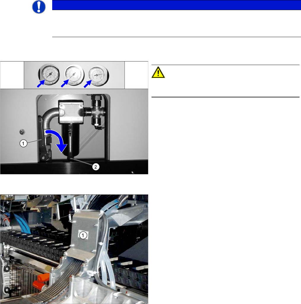
Disabling the compressed air supply
CAUTION!
When working on the pneumatic system, always switch
off the compressed air supply.
► Push the lever (1) for the compressed air supply
back, until it is positioned horizontally.
► Open the screw (2) on the inlet filter to vent the sys-
tem. Hold a cloth underneath to capture any escaping
oil.
► All manometers must be set to zero.
► Loosen the six screws fastening the cover (1) and
then remove the cover.