00197783-01_AI_Gantry-Retrofit_X-Series_S_INTERNAL_de_en.pdf - 第148页
Appendix Excerpts from the Service Manua l 4.1.6 Replacing the Proportiona l Controller (Location 4) [03065425-xx] 148 Gantry Retrofit Portalna chrüstung 1. Sealing adapter plate proportiona l controller [03083211 - xx] …
Appendix
4.1.6 Replacing the Proportional Controller (Location 4) [03065425-xx] Excerpts from the Service Manual
Gantry Retrofit Portalnachrüstung 147
4.1.6
4.1.6 Replacing the Proportional Controller (Location 4) [03065425-xx]
Replacing the Proportional Controller (Location 4) [03065425-xx]
Parts, Equipment and Tools
▪ Sealant adapter plate proportional valve [03083211-xx]
▪ In vacuum mode, when only one proportional controller is fitted:
Sealing plate for prop. valve (with O-rings) [03113039-xx]
▪ 3x ISO4762-M4x70-A2-70 [03082432-xx]
Overview
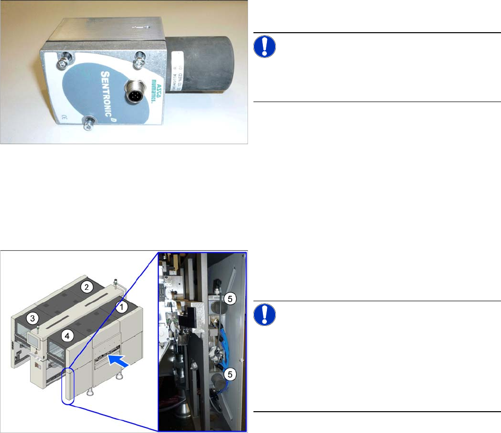
▪ Proportional controller Sentronic-D DN8 SUBB1/4
10 bar [03065425-xx] (pressure control valve)
NOTICE!
The proportional controller is supplied with the latest pa-
rameters preset. Subsequent programming is not possi-
ble.
1. to 4.: Location 1 to 4
5.: Proportional controller top and bottom
NOTICE!
Only one proportional controller is fitted for vacuum pump
mode (all heads).
When converting to compressed air mode (Twin and
CPP), you need to fit a second pressure control valve.
Read also the assembly instructions "SIPLACE X-Series
S, SX4/DX4 – Vacuum Pump" [DE+EN: 00196845-xx].
Appendix
Excerpts from the Service Manual 4.1.6 Replacing the Proportional Controller (Location 4) [03065425-xx]
148 Gantry Retrofit Portalnachrüstung
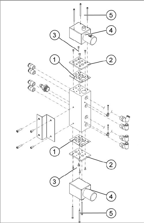
1. Sealing adapter plate proportional controller
[03083211-xx]
2. Adapter plate proportional controller
3. Fastening screws for adapter plate
Torque: 2.5 – 3.0 Nm
4. Proportional controller
5. Fastening screws for proportional controller
Torque: 2.0 – 2.5 Nm
Appendix
4.1.6 Replacing the Proportional Controller (Location 4) [03065425-xx] Excerpts from the Service Manual
Gantry Retrofit Portalnachrüstung 149
Removal
► Switch off the machine, disconnect it from the power supply and secure it to prevent unauthorized
reactivation. Observe the instructions in section "1.2 Preparatory Work..." [ ➙ 89].
Pneumatics Sy stem - Shutting off the Compressed Air Supply
► Disconnect the machine from the compressed air supply.
► To do this, loosen the screws fastening the side cover at location 4 and remove these. (see Disman-
tling the Lower Side Cover).
► Unplug the electrical connection to the proportional controller.
► Loosen the screws fastening the proportional controller and then remove the controller.
Installation
► Follow the removal instructions in reverse order for installation. Also observe the following instruc-
tions:
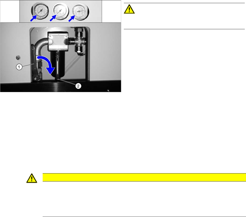
Disabling the compressed air supply
CAUTION!
When working on the pneumatic system, always switch
off the compressed air supply.
► Push the lever (1) for the compressed air supply
back, until it is positioned horizontally.
► Open the screw (2) on the inlet filter to vent the sys-
tem. Hold a cloth underneath to capture any escaping
oil.
► All manometers must be set to zero.
CAUTION
Installation instructions
► Clean the sealing rings and the adapter plate and insert these again. Observe the instruc-
tions in section Sealing the Screwed Connections in connection with this.
► Tighten the screws fastening the adapter plate and the proportional controller with a torque
of 2.0 to 2.5 Nm.