00197783-01_AI_Gantry-Retrofit_X-Series_S_INTERNAL_de_en.pdf - 第128页
Installation Attaching the Hoses to the Proportional Valve 3.1.4 Removing the Top C over 128 Gantry Retrofit Portalna chrüstung 3.9 3 . 9 A t t a c h in g t h e H o s e s t o t h e P r o p o r t io n a l V a lv e Attachi…
Installation
3.1.4 Removing the Top Cover Fitting the GCU
Gantry Retrofit Portalnachrüstung 127
3.8
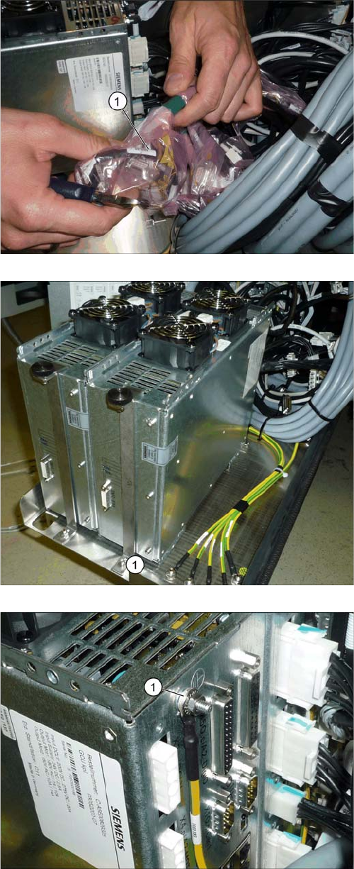
3.8 Fitting the GCU
Fitting the GCU
► Pull the rack for the GCUs out of the machine. To do
this, loosen the lockscrew on the bottom left of the
rack.
► Find the cable for the new GCU (1).
► Insert the new GCU into the machine and fix this into
place with the front holder (1).
► Fit the ground connection (1).
Installation
Attaching the Hoses to the Proportional Valve 3.1.4 Removing the Top Cover
128 Gantry Retrofit Portalnachrüstung
3.9
3.9 Attaching the Hoses to the Proportional Valve
Attaching the Hoses to the Proportional Valve
► Dismantle the lower side cover at location 4 (see "4.1.5 Dismantling the Lower Side Cover" [➙146]).
► Connect the two hoses (hold circuit and placement circuit) for the new gantry to the proportional
valve (see also "4.1.6 Replacing the Proportional Controller (Location 4) [03065425-xx]" [ ➙ 147]).
3.10
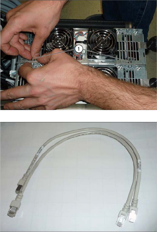
3.10 Attaching the Hotlink Cable
Attaching the Hotlink Cable
► Attach the hotlink cable P2 to the hotlink card in the BoxPC (see also "4.1.7 Overview of Distributor"
[ ➙ 150]).
► Connect the GCU to the adjacent GCU, using two
screws (1).
► Run the cables for the new GCU (see also "4.1.2
Overview of GCUs" [ ➙ 140]).
Use the patch cable supplied.
► Push the rack back into the machine.
► Fasten the rack with the lockscrew.
Installation
3.1.4 Removing the Top Cover Fitting the Covers etc.
Gantry Retrofit Portalnachrüstung 129
3.11
3.11 Fitting the Covers etc.
Fitting the Covers etc.
► Fit the lower side cover onto the proportional valve.
► Push the GCU rack into the machine and fasten it with the lockscrew at the bottom left.
► Make sure that none of the hoses or cables protrude out through the openings in the machine base.
► Fit the head and its accessories into place.
► Switch the machine on and check the pneumatic system for air-tightness.
► Fit the covers back on the trailing interface boards.
► Fit the cover on the placement area.
► Fit the middle cover back into place, including the monitor and keyboard.
► Fit the side cover/the guide on the service flap.
3.12
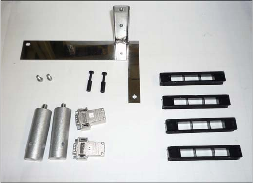
3.12 Parts No Longer Needed
Parts No Longer Needed
3.13
3.13 Final work
Final work
► Remove any remaining protective sleeves, covers etc.
► Check the setting of the Z incremental encoder on the new gantry (see also "4.1.3 Replacing the Y
Axis Incremental Encoder [03094996-xx]" [ ➙ 142]).
► Check the ID of the new gantry (see "4.2.3 Head Interface C700X-L/R HR" [ ➙ 155]).
3.14
3.14 Installing the Software
Installing the Software
► Install the station software. Read the relevant documentation for this.
– Installation Manual for Windows Embedded Standard 7 [00197366-xx]
The following parts will be left over after the conversion
work:
▪ 1x holder for trailing cover 2P down, incl. screws
▪ 2x pneumatic plugs (proportional valve)
▪ 2 x buffer
▪ 2x CAN terminal resistor
▪ 4x plastic holder for the trolley bearings