00197783-01_AI_Gantry-Retrofit_X-Series_S_INTERNAL_de_en.pdf - 第133页
Appendix 4.1.1 Replacing the Trailing Cable Excerpts from the Service Manual Gantry Retrofit Portalnachrüstung 133 4.1.1.1 4 . 1 . 1 . 1 H a n d lin g t h e H o s e U n lo c k in g T o o l [ 0 3 0 4 7 0 9 0 - x x ] Handl…
Appendix
Excerpts from the Service Manual 4.1.1 Replacing the Trailing Cable
132 Gantry Retrofit Portalnachrüstung
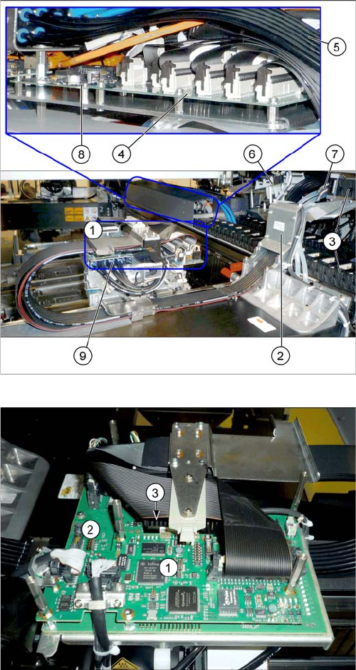
Overview
X34iS – Gantry – 1 Overview of Boards (Head Interface, Vision Board Spread Spectrum)
1. Boards on the gantry (shown without board cover
here)
2. Trailing cable console
3. Power track chain
4. Trailing interface gantry
5. Pneumatic hoses to the pneumatic distributor (in the
machine base)
6. Gantry interface
7. Connection piece for cooling tubes to Y motor
8. Vision Hotlink Adapter VHA [03050555-xx]
9. Pneumatic distributor
Boards on the gantry
1. Vision board spread spectrum / Vision Head Interface
(VHI)
2. Head interface
3. Power cube on the head interface
Appendix
4.1.1 Replacing the Trailing Cable Excerpts from the Service Manual
Gantry Retrofit Portalnachrüstung 133
4.1.1.1
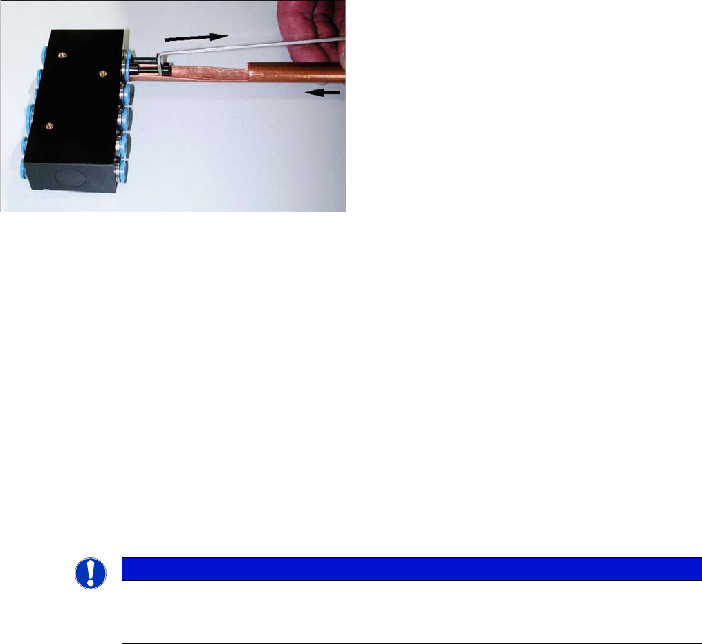
4.1.1.1 Handling the Hose Unlocking Tool [03047090-xx]
Handling the Hose Unlocking Tool [03047090-xx]
► Use the pipe-shaped tool (1) to open the unlocking ring.
► Carefully pull the hose out of the compressed air connection. The diagram shows the removal of a
dummy plug (2), not a hose.
4.1.1.2
4.1.1.2 Replacing the X Trailing Cable
Replacing the X Trailing Cable
Parts, Equipment and Tools
▪ X trailing cable (see above)
▪ Hose unlocking tool [03047090-xx]
▪ Pipe/hose cutters [00381443-xx]
▪ If required, assembly instructions for the "vacuum pump" [00196845-xx]
▪ Sealing varnish Loctite 241 [02101037-xx]
▪ Edding marker, white [00382740-xx]
▪ Help of second person, if needed
Removal
► Switch off the machine, disconnect it from the power supply and secure it to prevent unauthorized
reactivation. Observe the instructions in section "1.2 Preparatory Work..." [ ➙ 89].
Due to the poor access to the pneumatic distributor, we
recommend using an unlocking tool.
With the help of the hose unlocking tool [03047090-xx]
you can open the unlocking ring (blue here) for the com-
pressed air connection. This enables you to remove both
the hoses and the dummy plugs (additional tool "Unlock-
ing tool for QSC-10H" [03051853-xx]).
NOTICE
Vacuum pump
► When a vacuum pump is fitted, also observe the assembly instructions "Vacuum pump X-
Series S, SX4/DX4" [00196845-xx].
Appendix
Excerpts from the Service Manual 4.1.1 Replacing the Trailing Cable
134 Gantry Retrofit Portalnachrüstung
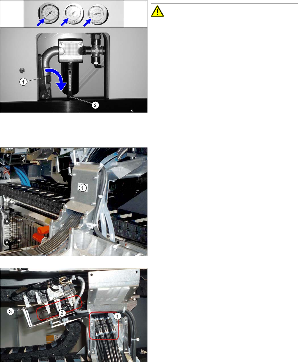
Pneumatics Sy stem - Shutting off the Compressed Air Supply
Loosening the trailing cable on the machine side
Disabling the compressed air supply
CAUTION!
When working on the pneumatic system, always switch
off the compressed air supply.
► Push the lever (1) for the compressed air supply
back, until it is positioned horizontally.
► Open the screw (2) on the inlet filter to vent the sys-
tem. Hold a cloth underneath to capture any escaping
oil.
► All manometers must be set to zero.
► Loosen the six screws fastening the cover (1) and
then remove the cover.
► Mark the positions of the hoses on both sides of the
couplings (1), so that these can be easily assigned
later on.
► Disconnect the hoses from the couplings.
► Mark the positions of the connectors (2) on the gantry
interface (3), so that these can be easily assigned lat-
er on.
► Unplug the connector from the gantry interface and
unthread the cable.