00197783-01_AI_Gantry-Retrofit_X-Series_S_INTERNAL_de_en.pdf - 第94页
Introduction Staff Qualifications and Training 1.3.4 Release History 94 Gantry Retrofit Portalna chrüstung 1.4 1 . 4 S t a f f Q u a lif ic a t io n s a n d T r a in in g Staff Qualifications and Training Qualified or ad…

Introduction
1.3.4 Release History Other Instructions
Gantry Retrofit Portalnachrüstung 93
1.3.3.3
1.3.3.3 Handling ESD Modules
Handling ESD Modules
Do not touch electronic modules unless it is absolutely essential to do so in order to carry out other work.
If it is necessary, make sure that you do not touch the pins or printed conductors when you pick up flat
modules.
Do not touch components unless
▪ You are constantly earthed by an ESD wrist strap or
▪ You are wearing ESD shoes or ESD shoe earthing strips on an ESD floor.
Always discharge yourself before you touch an electronic module. To do this, simply touch a conductive
and earthed object immediately before you touch the module (such as unpainted parts of a switch cab-
inet, a water pipe, etc.).
Do not allow modules with chargeable and highly insulating materials to touch one another, e.g. plastic
films, insulating table surfaces or items of clothing made from synthetic fibers.
Always place the modules on a conductive surface (table with an ESD coating, conductive ESD foam,
ESD bag or container).
Do not bring modules near visual display units, monitors or televisions. Keep them at least 10 cm away
from the screen.
1.3.3.4
1.3.3.4 Measurements and Modifications to ESD Modules
Measurements and Modifications to ESD Modules
Measurements of the assemblies may only be taken if
▪ The measuring device has been grounded (e.g. via protective conductor) or
▪ The measuring head of the potential-free measuring device has been briefly discharged before
measurement (e.g. touching blank metal control unit housing).
► Always use an earthed soldering iron if you carry out any soldering work.
1.3.3.5
1.3.3.5 Dispatching ESD Modules
Dispatching ESD Modules
► Always store modules and components in conductive packaging (e.g. metallized plastic bags or met-
al sleeves) and dispatch them in conductive packaging.
► If the packaging is not conductive, place the modules in a conductive envelope before packaging.
Use conductive foam rubber, ESD bags, domestic aluminum foil or paper, for example. NEVER use
plastic bags or film.
► If the module has integral batteries, ensure that the conductive packaging does not touch or short-
circuit the battery terminals and, if necessary, first cover the terminals with insulating tape or mate-
rial.
1.3.4
1.3.4 Release History
Release History
Document
SIPLACE X-Series S
Gantry retrofit (internal)
Assembly instructions
Edition Changes
07/2016 First edition
Introduction
Staff Qualifications and Training 1.3.4 Release History
94 Gantry Retrofit Portalnachrüstung
1.4
1.4 Staff Qualifications and Training
Staff Qualifications and Training
Qualified or adequately trained personnel means that these people are familiar with the setting up, op-
eration and maintenance of automatic placement systems and add-on devices and are suitably qualified,
e.g.:
▪ Have been trained, instructed or authorized to switch on and off, isolate, earth and identify electrical
circuits and system components in accordance with normal safety standards.
▪ Have been trained or instructed in the upkeep and use of appropriate safety equipment in accord-
ance with normal safety standards.
▪ Have received first aid training.
Brief Description
Gantries
Gantry Retrofit Portalnachrüstung 95
2
2 Brief Description
Brief Description
This section gives an overview of the product, the requirements, delivery scope, tools and working time
required.
2.1
2.1 Gantries
Gantries
2.2
2.2 Product Description
Product Description
A gantry retrofit enables you to upgrade a placement area with one gantry to a placement area with two
gantries.
The following upgrades are possible:
▪ SIPLACE X2 S → SIPLACE X3 S
▪ SIPLACE X2 S → SIPLACE X4 S (through a retrofit of both placement areas)
▪ SIPLACE X3 S → SIPLACE X4 S
2.3
2.3 Requirements
Requirements
A gantry retrofit can be performed in all SIPLACE X2 S and X3 S machines.
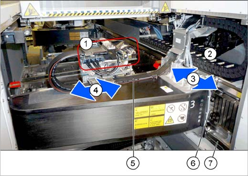
1. Head interface and Vision board
The Vision board is fitted onto the head interface.
2. Gantry trailing cables split for Y axis
3. Y-Axis
4. X axis
5. Gantry trailing cables split for X axis
6. Y drive (primary)
7. Y axis scale