SI-F130 Manual(EN)_jpg_ Rev1.pdf - 第10页
Install the Calibration Plate Jig HLF-10101-01 Install the Calibration Plate Jig SHEET 1/3 Inst all the Calibration Plate Jig Operations to use the cal ibration plate jig are as follows. When perform ing the following op…

CLF-10106-01
SI-F130 Service Manual
"Console Operation Procedure Con-
tents"
SHEET
2/2
2-4 Adjustment
Matching of X Axis Z-Phase...................................................... HLF-10401-01
Matching of Y Axis Z-Phase...................................................... HLF-10402-01
H Axis Gear Z-phase Matching ................................................. HLF-10403-01
Adjustment of H Axis Upper End OT Sensor (H-CCW)............. HLF-10404-01
Adjustment of H axis Lower End OT Sensor (H-CW) ...............HLF-10405-01
FF/FR Axis Z-Phase Matching.................................................. HLF-10406-01
Adjustment of FF/FR Axis Belt Tension..................................... HLF-10407-01
Adjustment of FF/FR Axis Feed Roller Y-Direction Position...... HLF-10408-01
Adjustment of FF/FR Axis Feed Roller Height .......................... HLF-10409-01
Position Adjustment for FF/FR Axis Feeder Backward
Detect Sensor ......................................................................... HLF-10410-01
Adjustment of FF/FR Axis Feed Roller Origin Sensor Dog ....... HLF-10411-01
Adjustment of FF/FR Axis Feed Roller X-Direction Position ..... HLF-10412-01
Adjustment of RT Axis Belt Tension .......................................... HLF-10413-01
Adjustment of RN Axis Belt Tension.......................................... HLF-10414-01
Gap Adjustment for Head Unit Mechanical Valve
and Plunger ............................................................................HLF-10415-01
Adjustment of Plunger Upper/Lower
Backward Detect Sensor ........................................................HLF-10416-01
Nozzle Omission Detection Sensor Position Adjustment .......... HLF-10417-01
Phase Adjustment for Nozzle.................................................... HLF-10418-01
Adjustment of PWB Sensor ...................................................... HLF-10419-01
Adjustment of Cassette Float Sensor Height ............................ HLF-10420-01
Adjustment of PWB Stopper Sensor ......................................... HLF-10421-01
Fixed Camera Parts Presence / Absence Sensor Setup ..........HLF-10422-01
Ejector Setup ............................................................................ HLF-10423-01
Adjustment of Bulk Unit Position............................................... HLF-10424-01
Blow Flow rate Setup................................................................ HLF-10425-01
Supplied Air Sensor Setup........................................................ HLF-10426-01
Vacuum Sensor Setup .............................................................. HLF-10427-01
Install the Calibration Plate Jig
HLF-10101-01
Install the Calibration Plate Jig
SHEET
1/3
Install the Calibration Plate Jig
Operations to use the calibration plate jig are as follows.
When performing the following operations, install the calibration plate jig according to the proce-
dure described in this section.
Set-Up
• RT Axis Origin Position Setup
• Acquiring Mounting Stroke Setup
• PWB Camera Setup
• Acquiring Mounting Locating Position Setup
Calibration
• PWB Camera Light Calibration
• Parts Camera Calibration
• Pickup Camera Calibration
• Fixed Camera Calibration
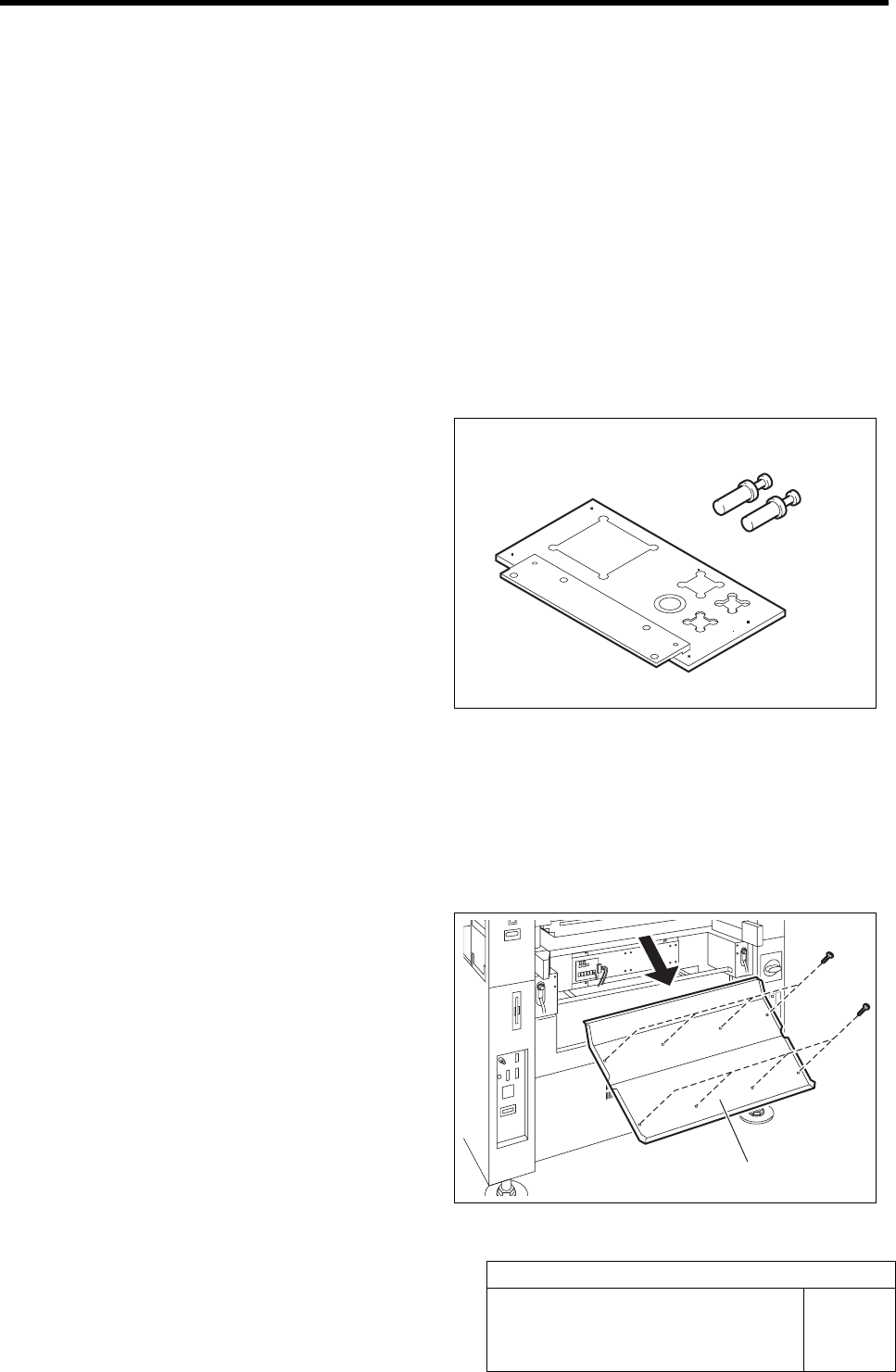
[Necessary jigs]
A Calibration plate jig
B Jig positioning pin
[Procedure]
1 Press the emergency stop switch to turn off the servo.
2 Turn off the interlock switch and open the front door.
3 Unscrew the 8 screws and remove the
shooter on the front side of the unit.
B
A
Shooter
Install the Calibration Plate Jig
HLF-10101-01
Install the Calibration Plate Jig
SHEET
2/3
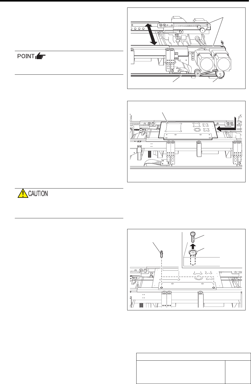
4 Manually move the pulley or belt for con-
veyor width adjusting motor to make the
width of the conveyor rail width to about the
width of calibration plate jig plus 0.5mm (ap-
proximately 120.5mm).
When in emergency stop status, the conveyor
width can be manually adjusted.
5 Install the calibration plate jig.
1. Place the calibration plate jig on the
rail on the right of the conveyor and
slide it to near the center of the con-
veyor.
2. Manually move the pulley or belt for
the conveyor width adjusting motor to
narrow the conveyor width.
3. Manually move the calibration plate
jig toward Y axis and check that
there’s slight rattle.
If installed with no gap between the calibra-
tion plate jig and rail, the calibration plate jig
may be deformed in clamping.
4. Insert the jig positioning pins (two)
into the calibration plate jig.
5. Remove the cap screw for jig position-
ing pin.
6 Turn the emergency stop switch in the arrow direction to release the emergency stop state.
Rail
Pulley Belt
Calibration plate jig
Jig positioning pin
Jig positioning pin
Cap screw