SI-F130 Manual(EN)_jpg_ Rev1.pdf - 第62页
Calibration Data Edit HLF-10310-01 Calibration Data Edit SHEET 1/1 Calibration Dat a Edit [Necessary jigs] 1 Display a Calibration Dat a Edit screen. 1. Click the Calibration Data Edit button on the CALIBRA TION screen. …
Parts Camera Calibration
HLF-10309-01
Parts Camera Calibration
SHEET
3/3
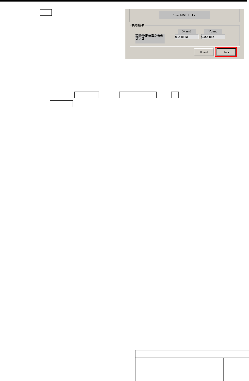
10 Click the Save button.
Information of the Auto calibration is saved and the
Auto calibration screen closes.
11 Remove the nozzle jig (AF80400) and jig chip.
1. Close the calibration screen.
2. Click in an order of MANUAL menuÎAXIS MOTION tabÎRT button.
3. Click the Jog Move button.
4. Press the left and right cursor keys to rotate the turrets, and remove all of the nozzle jig
(AF80400).
5. Remove the jig chips on the calibration plate jig.
Calibration Data Edit
HLF-10310-01
Calibration Data Edit
SHEET
1/1
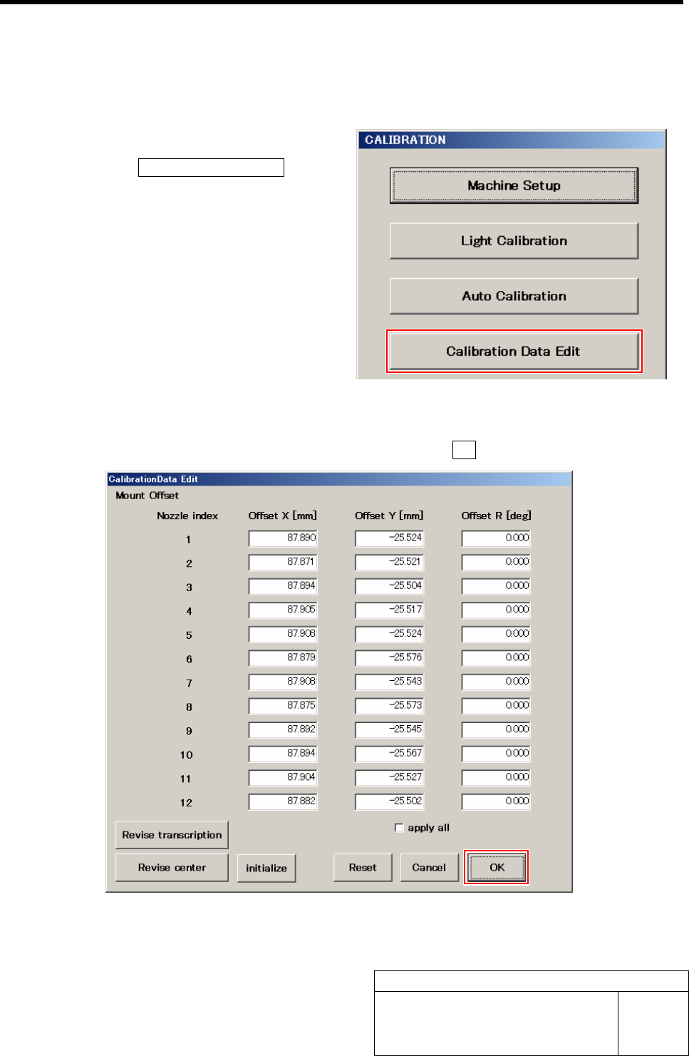
Calibration Data Edit
[Necessary jigs]
1 Display a Calibration Data Edit screen.
1. Click the Calibration Data Edit button
on the CALIBRATION screen.
Calibration Data Edit screen is displayed.
2 Change values of each offset obtained in the auto calibration.
1. Re-enter value in the box you want change, and click the OK button.
Pickup Camera Calibration
HLF-10311-01
Pickup Camera Calibration
SHEET
1/5
Pickup Camera Calibration
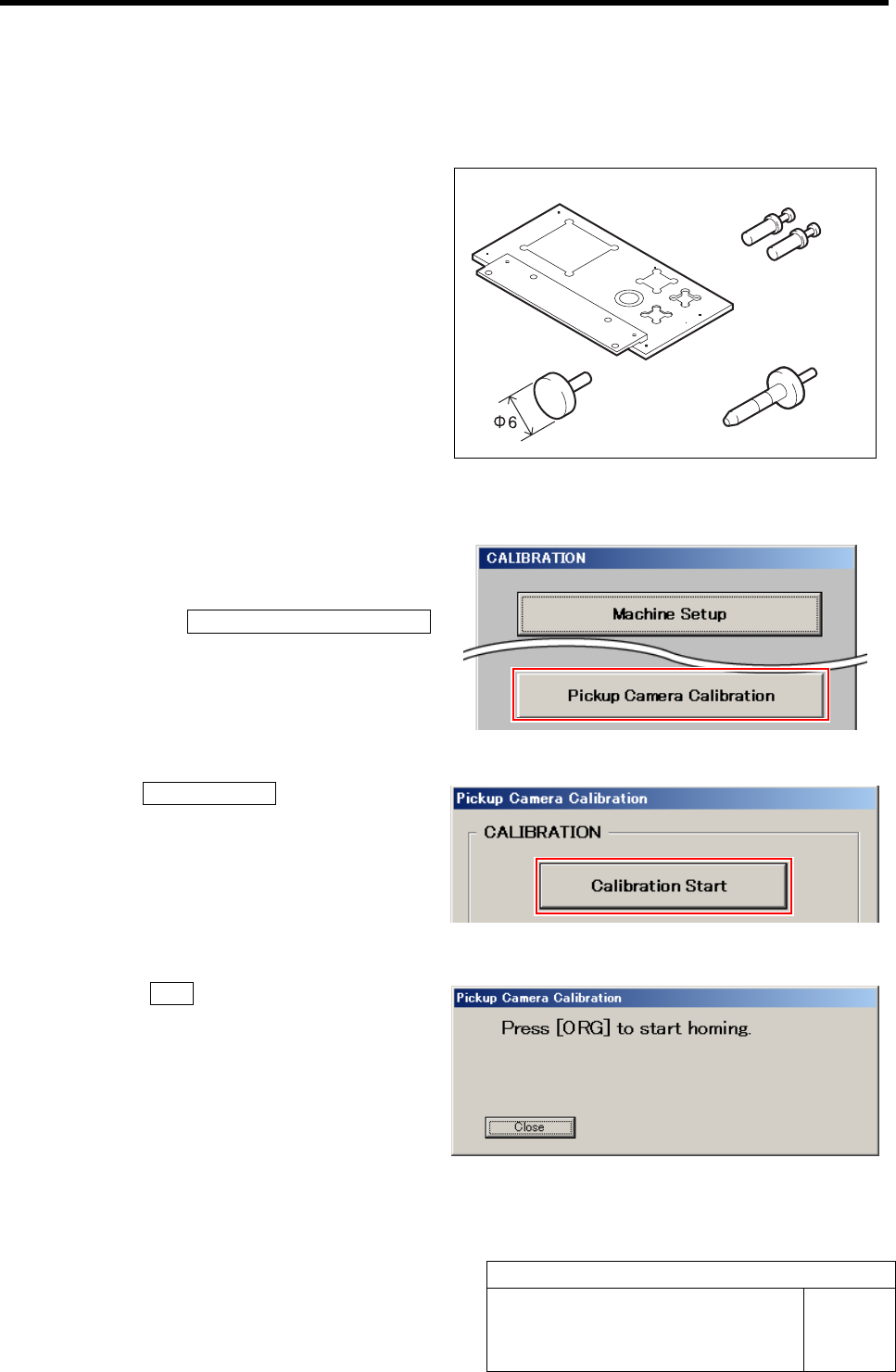
[Necessary jigs]
A Calibration plate jig
B Jig positioning pin
C Pickup inspection camera calibration jig
D Length reference nozzle jig
[Procedure]
1 Display a Pickup Camera Calibration
screen.
1. Click the Pickup Camera Calibration
button on the CALIBRATION screen.
Pickup Camera Calibration screen is displayed.
2 Click the Calibration Start button.
“Press [ORG] button to start homing” is displayed on
the message screen.
3 Press the ORG button on the operation
panel.
Origin position return is performed and “Install jig
onto plate” is displayed on the message screen.
AB
CD