SI-F130 Manual(EN)_jpg_ Rev1.pdf - 第154页
Fixed Camera Parts Presence/Absence S ensor Setup HLF-10422-01 Fixed Camera Parts Presence/ Absence Sensor Setup SHEET 2/4 2. Loosen 6 screws to remo ve the shooter on the back of the unit. 3. Loosen 2 cap screws on the …
Fixed Camera Parts Presence/Absence Sensor Setup
HLF-10422-01
Fixed Camera Parts
Presence/Absence Sensor Setup
SHEET
1/4
Fixed Camera Parts Presence/Absence Sensor Setup
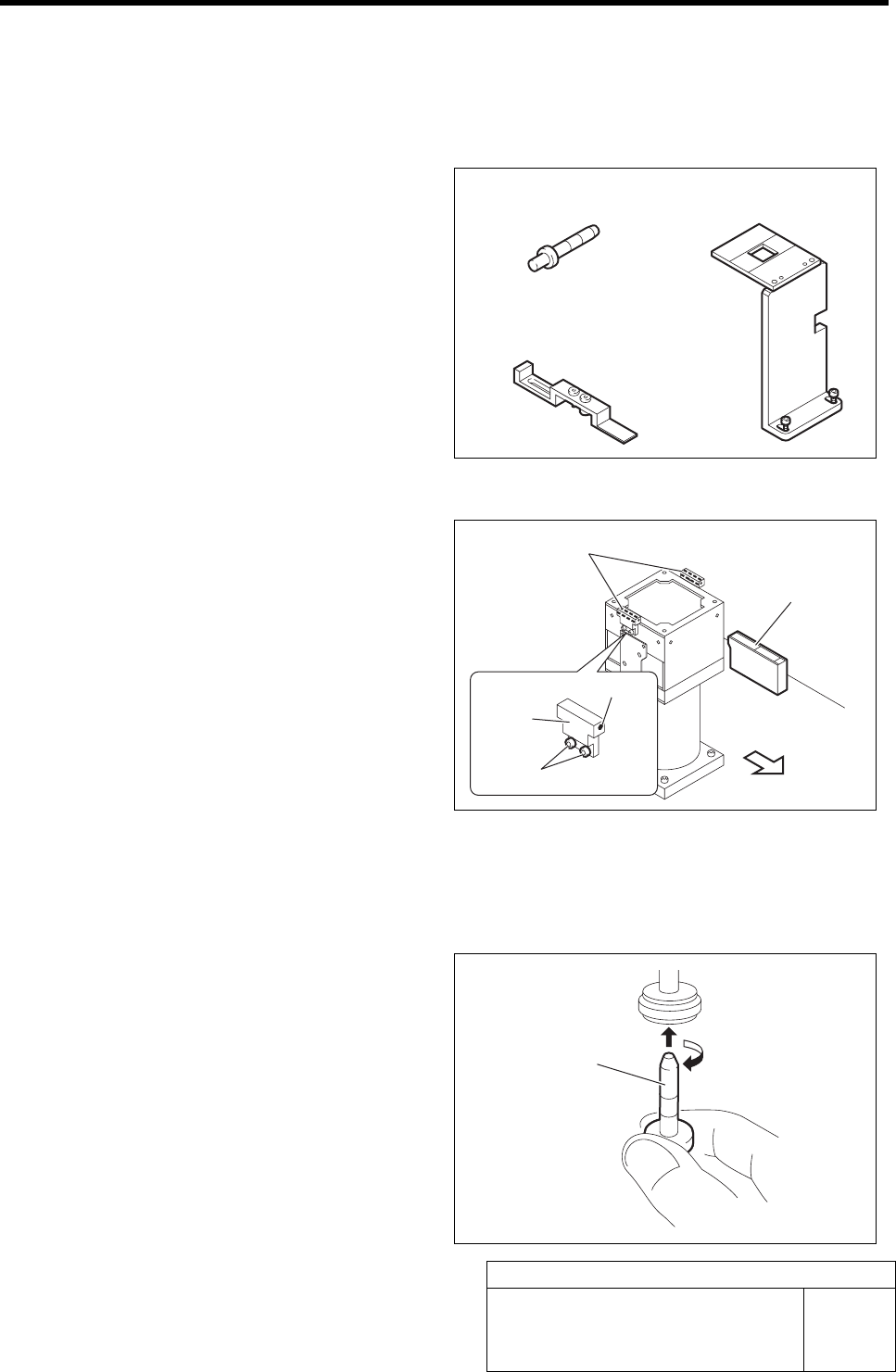
[Necessary jig]
• Nozzle jig for fixed camera
• Fixed camera parts presence/absence
sensor adjustment jig
• Fixed camera jig base
[Preparation before work]
1 Check that the displayed value on the parts
presence/absence sensor amplifier is “3800”
or more.
1. Check that the displayed value on the
parts presence/absence sensor ampli-
fier is “3800” or more.
When the displayed value is less than “3800”,
adjust the sensitivity according to the following
procedures 2. and 3.
2. Loosen the sensor bracket mounting
bolt, and move the sensor bracket up
and down, to left and right to adjust
the sensor mounting position.
3. Loosen the set screw to adjust the
sensor rotating direction.
2 Set the jig.
1. Install the Nozzle jig for fixed camera
to the turret No. 1.
Fixed camera jig base
Nozzle jig for fixed camera
Nozzle jig for fixed
camera
Fixed camera parts presence/
absence sensor
Front of unit
Set screw
Fixed camera parts presence/
absence sensor adjusting jig
Parts presence/
absence sensor
amplifier
Mounting bolt
Sensor
bracket
Fixed Camera Parts Presence/Absence Sensor Setup
HLF-10422-01
Fixed Camera Parts
Presence/Absence Sensor Setup
SHEET
2/4
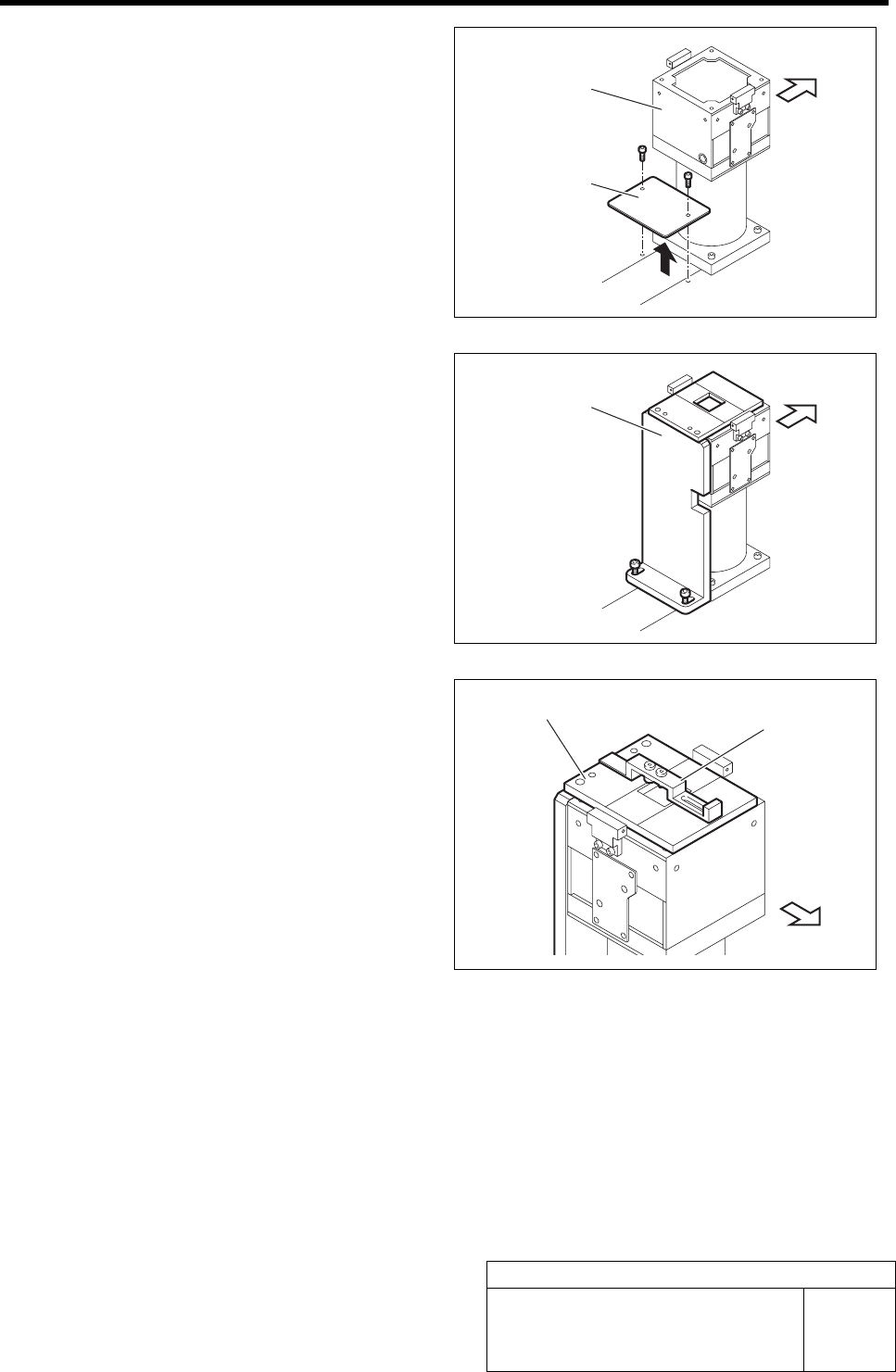
2. Loosen 6 screws to remove the shooter
on the back of the unit.
3. Loosen 2 cap screws on the back of the
fixed camera to remove the cover.
4. Fix the fixed camera jig base with the
2 cap screws.
5. Place the fixed camera parts pres-
ence/absence sensor adjusting jig on
the fixed camera jig base.
Cover
Fixed camera
Fixed camera jig base
Fixed camera
j
ig base
Fixed camera parts presence/
absence sensor adjusting jig
Front of unit
Front of unit
Front of unit
Fixed Camera Parts Presence/Absence Sensor Setup
HLF-10422-01
Fixed Camera Parts
Presence/Absence Sensor Setup
SHEET
3/4
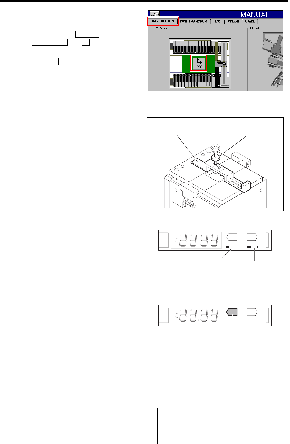
3 Move the nozzle jig onto the fixed camera
parts presence/absence sensor adjusting jig.
Click in an order of MANUAL menuÎ
AXIS MOTION tabÎXY button.
XY Axis screen is displayed.
1. Click the Jog Move button in the move
mode.
2. Press the cursor key to jog move the
nozzle jig onto the fixed camera parts
presence/absence sensor adjusting jig.
4 Press the emergency stop switch to turn off the servo.
5 Lower the turret No.1 by hand on which the
nozzle jig is mounted, and insert it into the
hole on the back of the fixed camera parts
presence/absence sensor adjusting jig to
perform positioning.
6 Turn the ADJ switch on the parts presence/
absence sensor amplifier to the “SET” side.
1. Open the cover of the parts presence/
absence sensor amplifier.
2. Switch the ADJ switch to the “SET”
side.
3. Check that the operation mode selector
switch is on the “L” side (Light ON).
TEACH
ADJ
SET RUN
LD
MODE
7 Lower the nozzle jig by hand, and press the
TEACH button on the parts presence/
absence sensor amplifier for long time.
Check that the display state changes from red light-
ing-up to green lighting-up.
TEACH
ADJ
SET RUN
LD
MODE
Fixed camera parts presence/
absence sensor adjusting jig
Nozzle jig for
fixed camera
ADJ switch
Operation mode selector switch
TEACH button