SI-F130 Manual(EN)_jpg_ Rev1.pdf - 第85页
Pickup Position Setup HLF-10314-01 Pickup Position Setup SHEET 7/7 7 Set the calculated position dat a. 1. Click the Return button on the Front/All Cass. Pos. T eaching by T ools screen to close the scr een. 2. Check the…
Pickup Position Setup
HLF-10314-01
Pickup Position Setup
SHEET
6/7
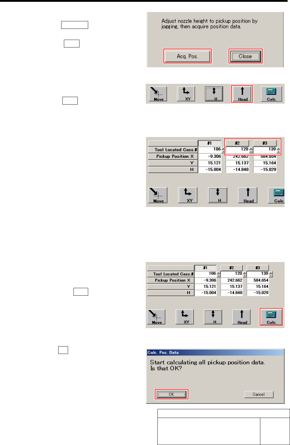
3 Acquire the H position after positioning.
1. Click the Acq. Pos. button on the H
screen to acquire H position of Z106.
2. Click the Close button to close H
screen.
4 Move the head away.
1. Click the Head button to move the
head away from the pickup position.
This completes acquiring H position data for
Z106.
5 Perform XY position data teaching and H
position data teaching at Z120 and Z139.
1. Move the pickup point jig to the posi-
tions of Z120 and Z139.
2. Input “120” to #2, “139” to #3 on the
Front/All Cass. Pos. Teaching by Tools
screen.
3. Acquire pickup position data of Z120
and Z139 in the same procedure as
those in the “XY Position Data Teach-
ing” and “H Position Data Teaching
(procedure 1 to 4).
6 Calculate the pickup position data.
1. After acquiring the pickup position
data at three points of Z106, Z120 and
Z139, click the Calc. button.
Confirmation window for calculating position
data.
2. Click the OK button.
Calculation for position data is performed.
Pickup Position Setup
HLF-10314-01
Pickup Position Setup
SHEET
7/7
7 Set the calculated position data.
1. Click the Return button on the
Front/All Cass. Pos. Teaching by Tools
screen to close the screen.
2. Check the Set button for the Front
Pos. Data is displayed in blue letter.
Unless the Set button is displayed in blue,
position calculation is not performed.
Again, perform “Acq.Pos.” or “Calc.”.
3. Click the Set button.
Confirmation window for setting is displayed.
4. Click the Update button.
X, Y, H position data for parts pickup position is
updated.
5. Check that the front position data
value was updated.
8 Set up the rear position data in the same procedure as that for the front position data setup (XY
position data teaching, H position data teaching)
Measuring locations of the rear position data are “Z202” for #1, “Z220” for #2 and “Z235” for #3.
Software Limit Setup
HLF-10315-01
Software Limit Setup
SHEET
1/7
Software Limit Setup
[Necessary jigs]
• Do not use jig.
[Procedure]
In order to set up software limit, it is necessary to change the default value at first so that the
software limit does not function.
Before setting up the software limit, change the default values of the software limit according to the
following procedure.
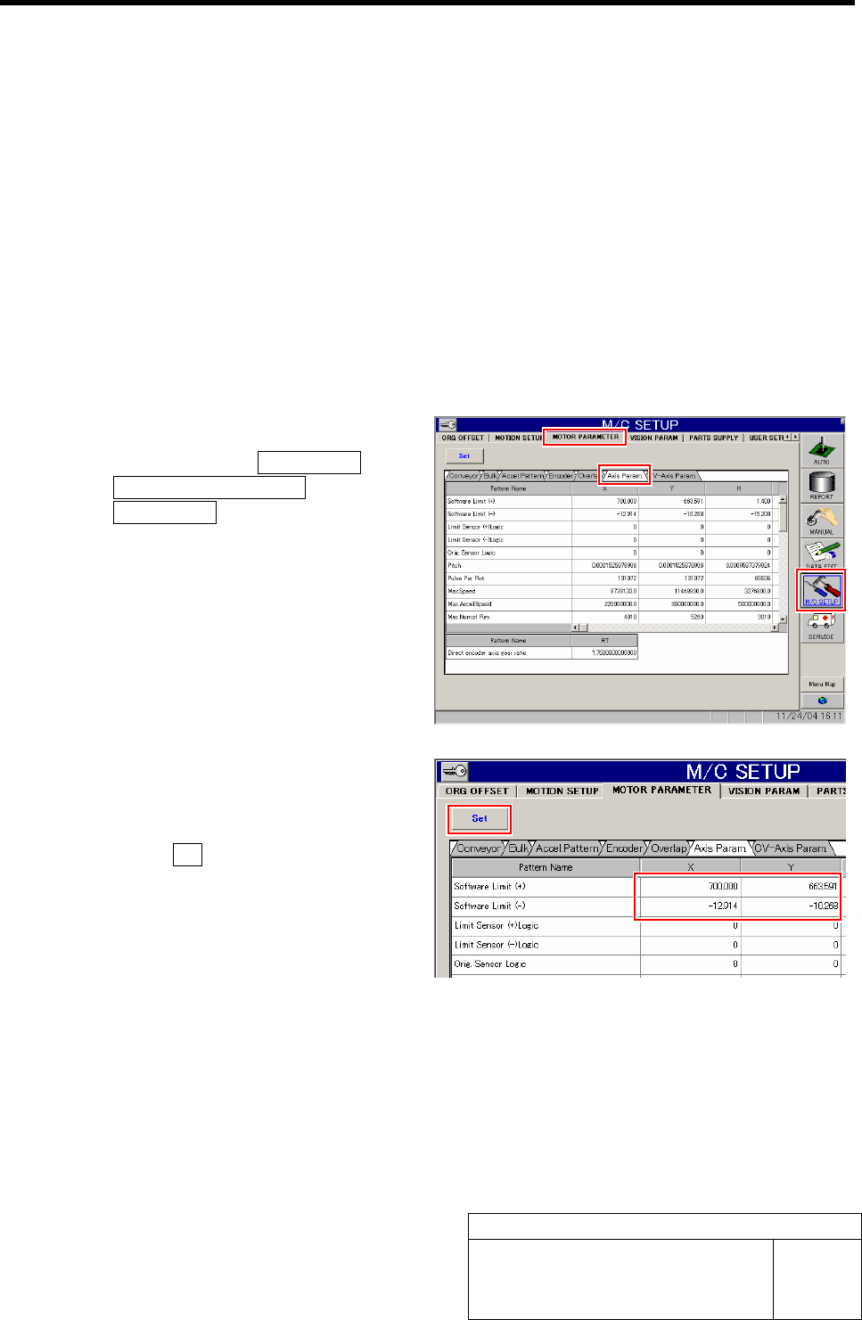
1 Change the default value of the software.
1. Click in an order of M/C SETUP men
ÎMOTOR PARAMETER tab
ÎAxis Param. tab.
Axis Parameter screen is displayed.
2. Input values for which “100” is respec-
tively added to software limit +/- val-
ues of XY axis.
3. Click the Set button.
The updated software limit values are saved.