SI-F130 Manual(EN)_jpg_ Rev1.pdf - 第27页
Acquiring Mounting Stroke Setup HLF-10203-01 Acquiring Mounting S troke Setup SHEET 3/3 6 Adjust gap between the length reference nozzle jig and calibration plate jig. 1. Click the R.H button on the Acquirin g mounting s…
Acquiring Mounting Stroke Setup
HLF-10203-01
Acquiring Mounting Stroke Setup
SHEET
2/3
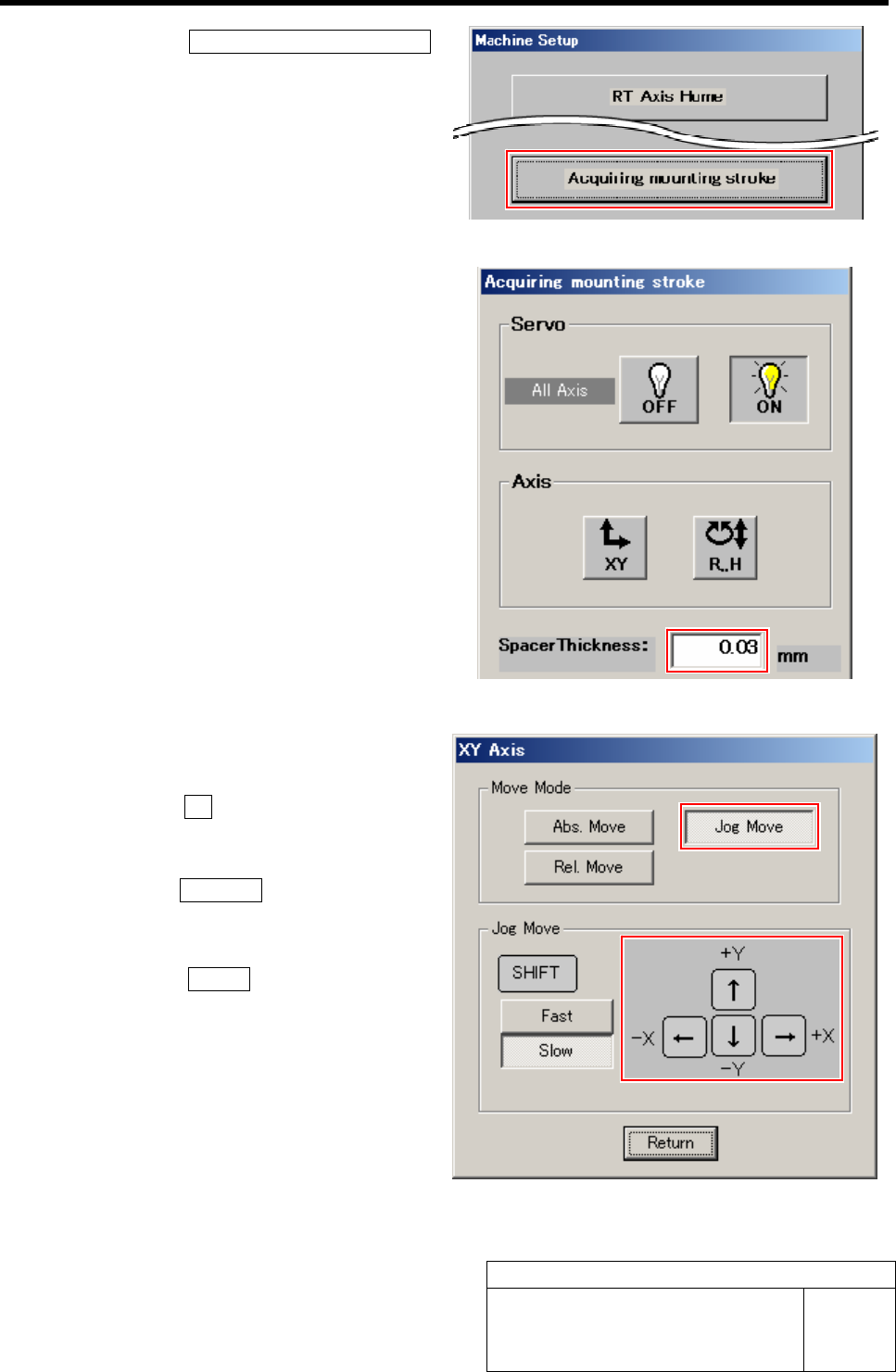
3. Click the Acquiring mounting stroke
button on the Machine Setup screen.
Acquiring mounting stroke screen is displayed.
4 Enter thickness (0.03 mm) of thickness
gauge used for placement height adjustment
in a space box on the Acquiring mounting
stroke screen.
5 Move the head unit onto the calibration plate
jig.
1. Click the XY button on the Acquiring
mounting stroke screen.
XY Axis screen is displayed.
2. Click the Jog Move button.
3. Press the cursor key to jog move the
head unit onto the calibration plate jig.
4. Click the Return button to return to
the Acquiring mounting stroke screen.
Acquiring Mounting Stroke Setup
HLF-10203-01
Acquiring Mounting Stroke Setup
SHEET
3/3
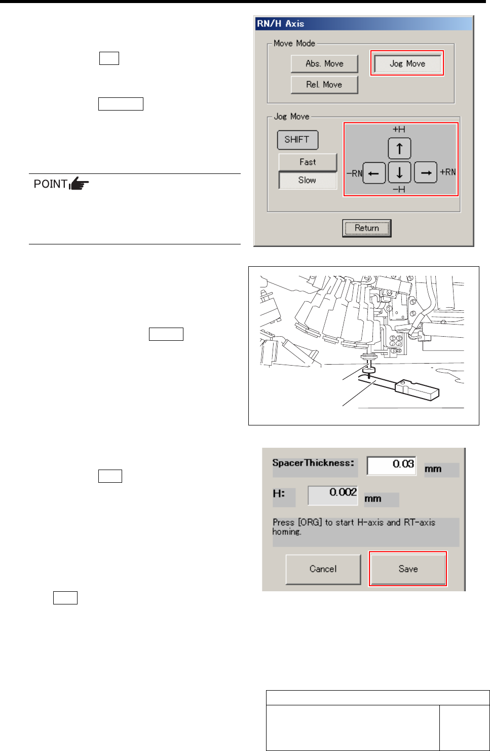
6 Adjust gap between the length reference
nozzle jig and calibration plate jig.
1. Click the R.H button on the Acquiring
mounting stroke screen.
RN/H Axis screen is displayed.
2. Click the Jog Move button.
3. Press the downward cursor key and
lower until the gap between the length
reference nozzle jig and calibration
plate jig becomes 0.03mm.
Slowly lower by Jog slow move while
checking the nozzle position so that the
length reference nozzle jig does not collide
he calibration plate jig.
4. Check the gap between the length ref-
erence nozzle jig and calibration plate
jig using thickness gauge of 0.03mm.
5. After completing to adjust the gap of
0.03mm, press the Return button on
the RN/H Axis screen to return to the
Acquiring mounting stroke screen.
7 Save the H axis height (placement height).
1. Click the Save button.
The adjusted H axis height is saved and the value
of “NOZZLE_S” in calib.ini file is updated.
8 Remove the length reference nozzle jig.
1. Return to the HI screen and press the
ORG button on the operation panel.
All axes return to origin.
2. Remove the length reference nozzle jig
from the turret No.1.
Thickness gauge
Length reference
nozzle jig
PWB Camera Setup
HLF-10204-01
PWB Camera Setup
SHEET
1/4
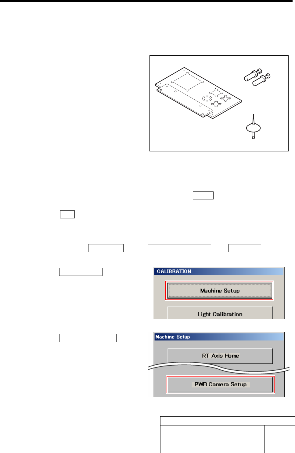
PWB Camera Setup
[Necessary jigs]
• Calibration plate jig
• Jig positioning pin
• Nozzle jig (AF06040)
[Procedure]
1 Perform the origin position return on the HI screen.
1. When the CALIBRATION screen is displayed, press the Return button to return to the HI
screen.
2. Press the ORG button on the operation panel.
Origin position return is performed.
2 Display PWB Camera Setup screen.
1. Click in an order of M/C SETUP menuÎM/C MAINTENANCE tabÎCalibration button.
CALIBRATION screen is displayed.
2. Click the Machine Setup button.
Machine Setup screen is displayed.
3. Click the PWB Camera Setup button.
PWB Camera Setup screen is displayed.
Calibration plate jig
Nozzle jig (AF06040)
Jig positioning pin