SI-F130 Manual(EN)_jpg_ Rev1.pdf - 第141页
Phase Adjustment for Nozzle HLF-10418-01 Phase A djust ment for Nozzle SHEET 2/8 2 Remove all of the mechanical valves. 1. Loosen 2 cap screws to remove the mechanical valve. 2. Manually turn the turret and r emove the m…
Phase Adjustment for Nozzle
HLF-10418-01
Phase Adjustment for Nozzle
SHEET
1/8
Phase Adjustment for Nozzle
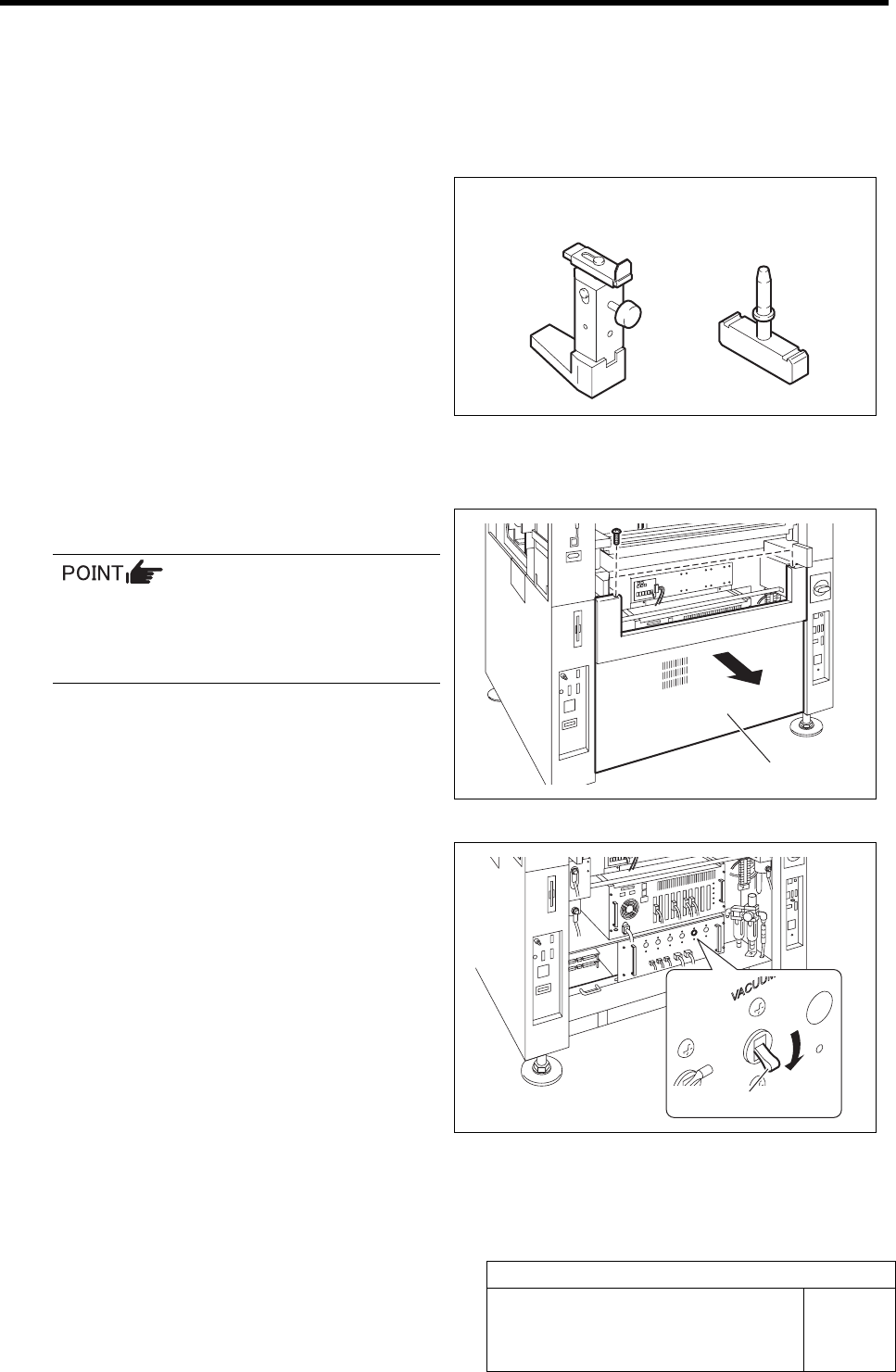
[Necessary jigs]
• Phase adjusting jig for nozzle
• Phase adjusting jig
[Procedure]
1 Turn OFF the VACUUM breaker.
In order to prevent suction of contaminant
and dust from mechanical valve, turn OFF
the VACUUM breaker before removing the
mechanical valve.
1. Loosen 2 screws to remove the lower
panel on the front of the unit.
2. Turn OFF the VACUUM breaker in
the PC unit.
Lower panel
VACUUM breaker
Phase adjusting jig
for nozzle
Phase adjusting jig
Phase Adjustment for Nozzle
HLF-10418-01
Phase Adjustment for Nozzle
SHEET
2/8
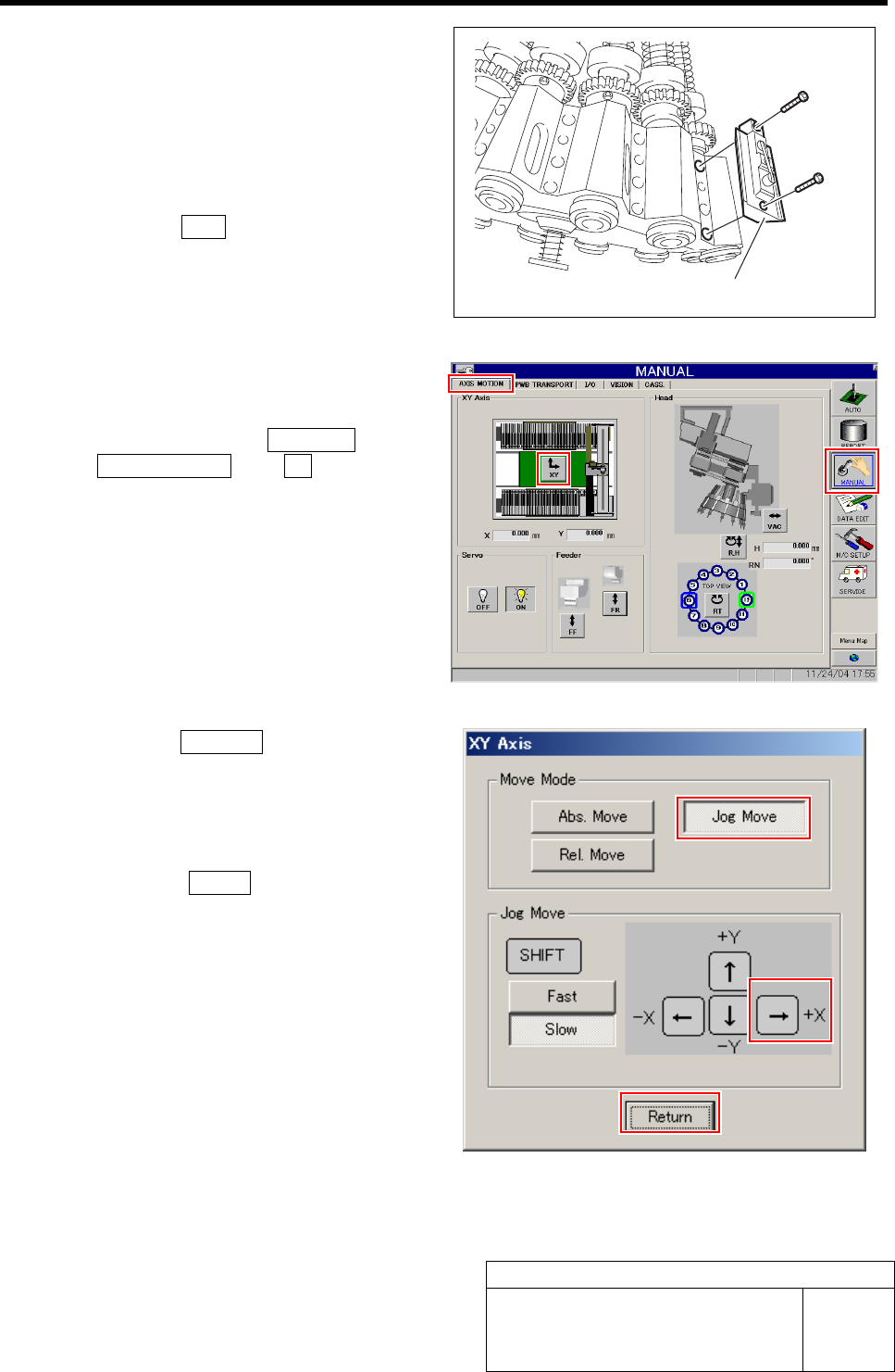
2 Remove all of the mechanical valves.
1. Loosen 2 cap screws to remove the
mechanical valve.
2. Manually turn the turret and remove
the mechanical valves sequentially.
3 Perform origin position return of the unit.
1. Press the ORG button on the operation
panel with the HI screen being dis-
played.
4 Manually move the head unit to a position of
the center on the left and right of the X axis.
1. Click in an order of MANUAL menuÎ
AXIS MOTION tabÎXY button.
XY Axis screen is displayed.
2. Click the Jog Move button in the move
mode.
3. Press the right cursor key to jog move
the head unit to the center position on
the left and right.
4. Click the Return button to close the
XY Axis screen.
Mechanical valve
Phase Adjustment for Nozzle
HLF-10418-01
Phase Adjustment for Nozzle
SHEET
3/8
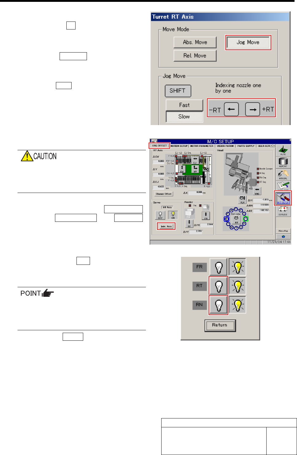
5 Move the turret No.1 to the front.
1. Click the RT button on the Axis
MOTION screen.
Turret RT Axis screen is displayed.
2. Click the Jog Move button.
3. Press the left and right cursor key to
move the turret No.1 to the front.
Click the Return button to close the Turret RT
Axis screen.
6 Turn off the RN, RT servos.
If working is carried out without turning off
the servo, hand or fingers may be caught in
the small gear. Be sure to turn OFF the
servo before working.
1. Click in an order of M/C SETUP
menuÎORG OFFSET tabÎIndv. Axis
button.
Indv. Axis servo screen is displayed.
2. Click the servo OFF button for RT and
RN.
Servo for RT, RN is turned off.
When servo is turned off, the button may
respond slowly. Securely click the button
to check that the indication changes to
indication of button being pressed.
3. Click the Return button to close the
Indv. Axis servo screen.