SI-F130 Manual(EN)_jpg_ Rev1.pdf - 第170页
3 Mechanical Layout
Vacuum Sensor Setup
HLF-10427-01
Vacuum Sensor Setup
SHEET
2/2
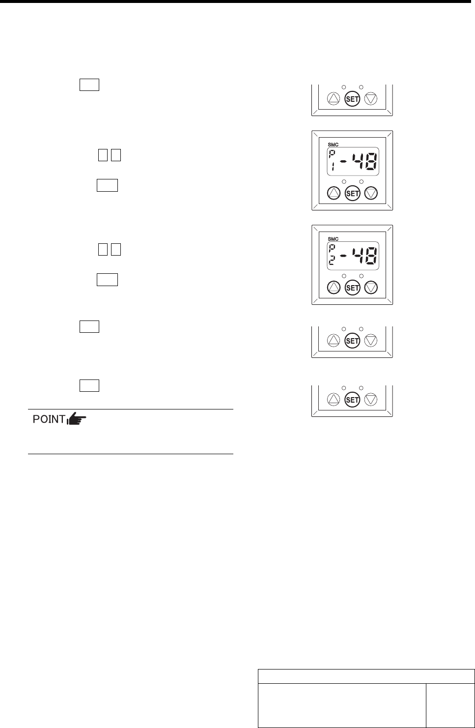
[Pressure setting Procedure]
Set the set value for each mode selected by the initial setting.
1 Press the SET button.
“P_1” and the set value are alternately displayed.
2 Set the set value for the output mode (P1).
1. Press the c d button to set the value
to “-48”.
2. Press the SET button.
“P_2” and the set value are alternately displayed.
3 Set the set value for the output mode (P2).
1. Press the c d button to set the value
to “-48”.
2. Press the SET button.
“P_3” and the set value are alternately displayed.
4 Press the SET button.
“P_4” and the set value are alternately displayed.
5 Press the SET button.
Return to the Measurement mode.
Because the output modes (P3) and (P4)
are not used, do not set the values.
3 Mechanical Layout
CLF-10107-01
SI-F130 Service Manual
"Mechanical Layout Contents"
SHEET
1/1
Contents
3 Mechanical Layout
General Drawing....................................................................... LAF-10101-01
PC Unit ..................................................................................... LAF-10102-01
Power Unit ................................................................................ LAF-10103-01
Servo I/F Unit............................................................................ LAF-10104-01
I/O Unit ..................................................................................... LAF-10105-01
Driver Unit................................................................................. LAF-10106-01
X-axis and Y-axis Circumference .............................................. LAF-10107-01
Head Unit Circumference ......................................................... LAF-10108-01
Front Supply Unit Circumference.............................................. LAF-10109-01
Rear Supply Unit Circumference .............................................. LAF-10110-01
Operation Panel Circumference.................................................LAF-10111-01
Machine Top Circumference ..................................................... LAF-10112-01
Transfer Unit Connector and Motor .......................................... LAF-10113-01
Transfer Unit Sensor................................................................. LAF-10114-01
Transfer Unit Cylinder ............................................................... LAF-10115-01
Transfer Unit Valve ................................................................... LAF-10116-01
Transfer Unit Rear Circumference ............................................ LAF-10117-01
Front Side Feeder Unit ............................................................. LAF-10118-01
Rear Side Feeder Unit .............................................................. LAF-10119-01
Machine Side............................................................................ LAF-10120-01
Connector Panel (XY Unit Part)................................................ LAF-10121-01
Interface Panel ......................................................................... LAF-10122-01