SI-F130 Manual(EN)_jpg_ Rev1.pdf - 第119页
Adjustment of FF/FR Axis Feed R oller Height HLF-10409-01 Adjustment of FF/FR Axis Feed Roller Height SHEET 2/2 4 Loosen the cap screws (2-M4) and lock nuts (N3) on the feed roller p art. 1. Loosen the cap scre ws (2-M4)…
Adjustment of FF/FR Axis Feed Roller Height
HLF-10409-01
Adjustment of FF/FR Axis Feed
Roller Height
SHEET
1/2
Adjustment of FF/FR Axis Feed Roller Height
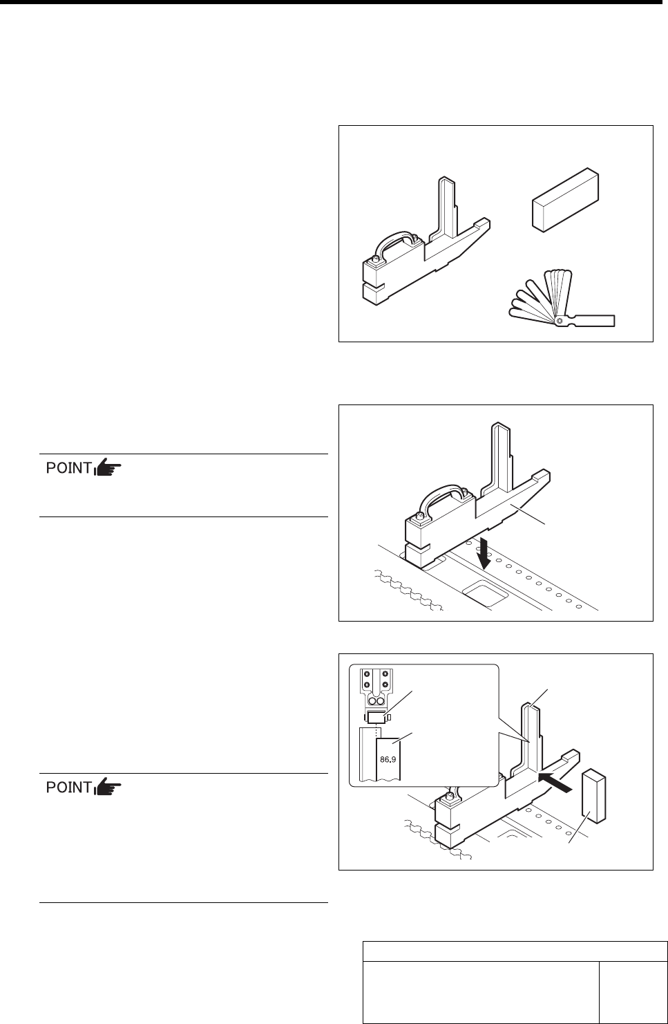
[Necessary jigs]
• Feed adjusting jig
• Part feed height jig
• Thickness gauge
[Procedure]
1 Set the feed adjusting jig to the No.20 posi-
tion on the cassette table.
There should be no clearance between the
feed adjusting jig and the cassette table.
2 Place a part feed height jig on the feed ad-
justing jig.
3 Adjust the position of the part feed height jig
so that the part feed height jig end face
matches the center of the feed roller.
The cassette feed lever is fed in the center
of the roller, however, the roller tends to be
fed in the above right direction, then, ad-
just the position of the part feed height jig
between the jig end face and the roller
center.
Feed adjusting jig
Part feed height jig
Thickness gauge
Feed adjusting jig
Feed adjusting jig
Part feed height jig
Feed roller
Part feed
height jig
Adjustment of FF/FR Axis Feed Roller Height
HLF-10409-01
Adjustment of FF/FR Axis Feed
Roller Height
SHEET
2/2
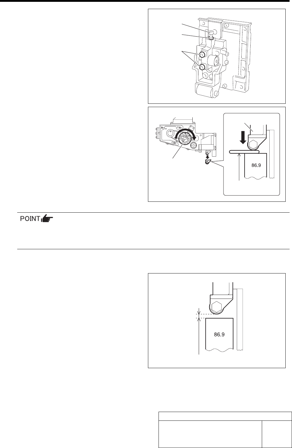
4 Loosen the cap screws (2-M4) and lock nuts
(N3) on the feed roller part.
1. Loosen the cap screws (2-M4) with a
short end 3 mm wrench.
2. Loosen the lock nuts (N3) with a 5.5
mm spanner.
5 Adjust the height of the feed roller lowest
point.
1. Turn the driven pulley clockwise and
stop the feed roller at the lowest point.
2. Insert the thickness gauge of t = 0.1
mm between the feed roller and part
feed height jig.
3. Fasten the cap screws (M3) until the
feed roller contacts the thickness
gauge.
• The clearance can be adjusted to slightly narrower than 0.1 mm by contact of the thickness
gauge with the feed roller.
• Turn the driven pulleys and dog for both of the FF axis/FR axis clockwise.
4. Fasten the cap screws (2-M4) and lock nut (N3) on the feed roller part.
5. Remove the thickness gauge.
6 Recheck the height of the feed roller lowest
height.
1. Turn the driven pulley clockwise and
stop the feed roller at the lowest point.
2. Check that thickness gauge of t = 0.1
mm cannot be inserted between the
feed roller and the part feed height
jig.
3. Check that there is a clearance be-
tween the feed roller and the part feed
height jig.
7 Relocate the jig to the No.1 and 40 position on the cassette table, and check that thickness gauge of
t = 0.15 mm cannot be inserted between the feed roller and the part feed height jig.
M3
N3
M4
Thickness gauge of t=0.1 mm should not be inserted
Thickness gauge
(t = 0.1 mm)
Feed roller
Driven pulley
Position Adjustment for FF/FR Axis Feeder Backward Detect Sensor
HLF-10410-01
Position Adjustment for FF/FR Axis
Feeder Backward Detect Sensor
SHEET
1/2
Position Adjustment for FF/FR Axis Feeder Backward Detect Sensor
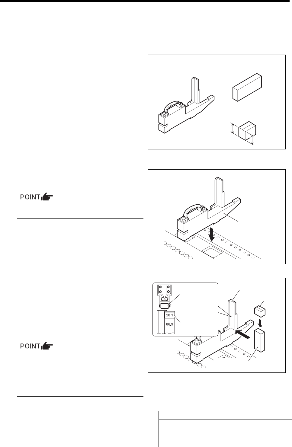
[Necessary jigs]
• Feed adjusting jig
• Part feed height jig
• F axis return block (20.6 mm, 20.1 mm)
[Procedure]
1 Set the feed adjusting jig to the No.20 posi-
tion on the cassette table.
There should be no clearance between the
feed adjusting jig and the cassette table.
2 Place the part feed height jig and F axis re-
turn block on the feed adjusting jig.
3 Adjust the position so that end face of the
lower side (20.1 mm) of the F axis return
block matches with the center of the feed
roller.
The cassette feed lever is fed in the center
of the roller, however, the roller tends to be
fed in the above right direction, then, ad-
just the position of the part feed height jig
between the jig end face and the roller
center.
Feed adjusting jig
Part feed height jig
F axis return block
Feed adjusting jig
Feed adjusting jig
Part feed height jig
Feed roller
F axis return
block
F axis return block
20.6 mm
20.1 mm