SI-F130 Manual(EN)_jpg_ Rev1.pdf - 第70页
Fixed Camera Rcg Heig ht Calibration HLF-10312-01 Fixed Camera Rcg Height C alibration SHEET 3/4 10 Install the length reference nozzle jig. 1. Click the Y es button. ”Press [ST AR T] to move to nozzle installing po- sit…
Fixed Camera Rcg Height Calibration
HLF-10312-01
Fixed Camera Rcg Height Calibration
SHEET
2/4
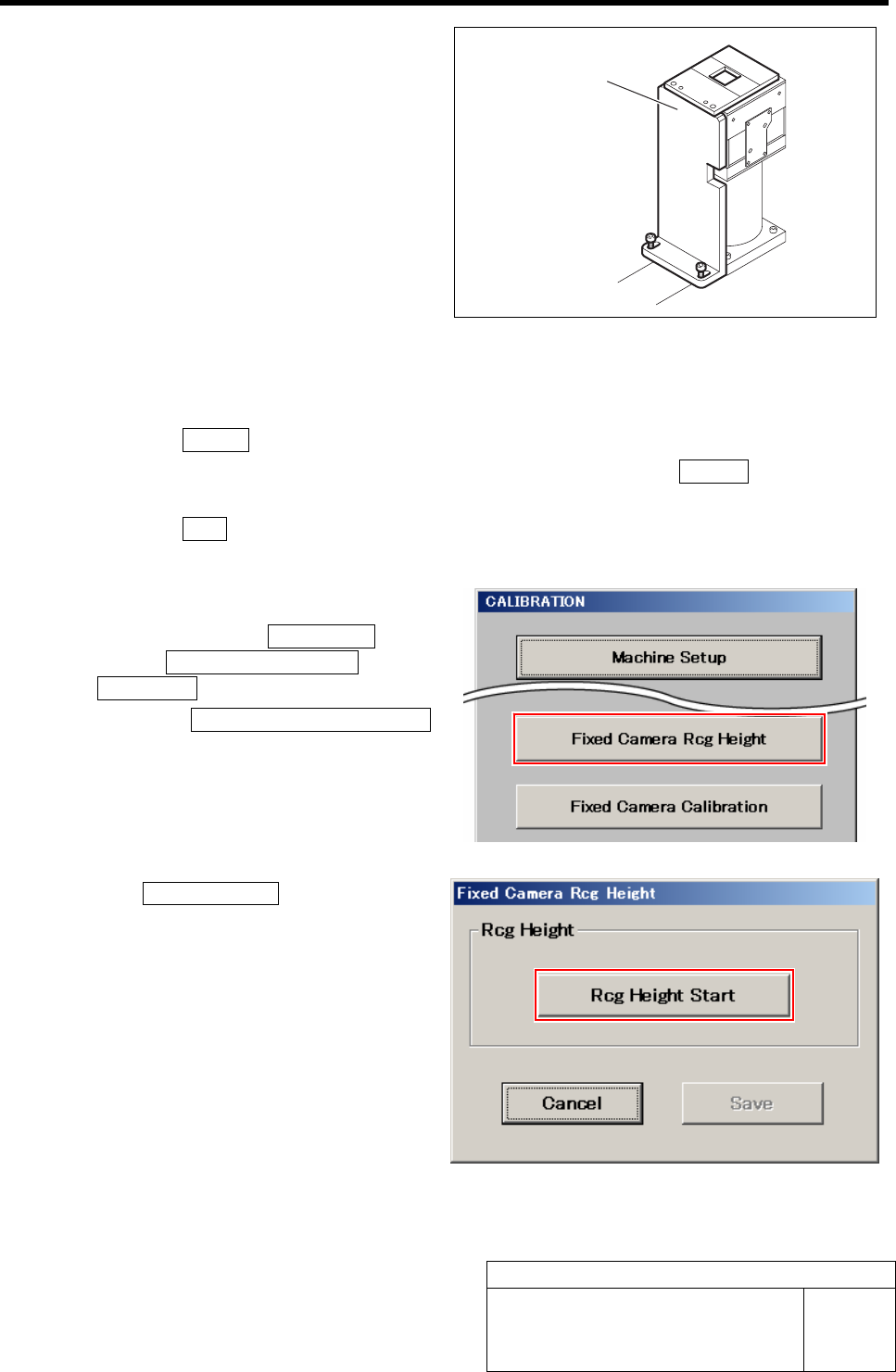
5 Secure the fixed camera jig base with 2
screws.
6 Turn the emergency stop switch in the arrow direction to release the emergency stop state.
7 Perform the origin position return.
1. Press the RESET button on the operation panel to perform the initialization.
2. When “SYMC Initialize End” is displayed on the screen, press the FRONT button to turn
ON the servo.
3. Press the ORG button on the operation panel to start the origin position return.
When the origin position return is completed, the ORG button goes off.
8 Display a Fixed Camera Rcg Height screen.
1. Click in an order of M/C SETUP
menuÎM/C MAINTENANCE tabÎ
Calibration button.
2. Click the Fixed Camera Rcg Height
button on the CALIBRATION screen.
Fixed Camera Rcg Height screen is displayed.
9 Click the Rcg Height Start button.
“Install nozzle?” is displayed on the message
screen.
Fixed camera jig base
Fixed Camera Rcg Height Calibration
HLF-10312-01
Fixed Camera Rcg Height Calibration
SHEET
3/4
10 Install the length reference nozzle jig.
1. Click the Yes button.
”Press [START] to move to nozzle installing po-
sition” is displayed on the message screen.
2. Press the START button on the opera-
tion panel.
Turret No.1 moves to the nozzle installing posi-
tion.
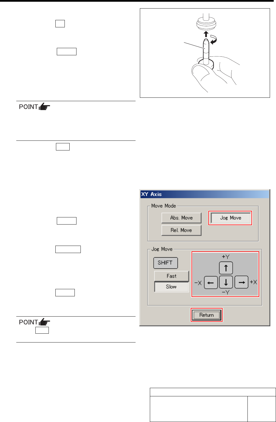
3. Install the length reference nozzle jig
to the turret No.1.
When installing the nozzle, insert it while
slowly turning.
After inserting the nozzle, check that it is
not drawn out by pulling downward.
4. Press the ORG button on the operation
panel.
Origin position return is performed and “Move
nozzle tip to fixed camera position” is displayed
on the message screen.
11 Move the length reference nozzle jig in-
stalled on the turret No.1 onto the fixed
camera jig base.
1. Press the START button on the opera-
tion panel.
XY Axis screen is displayed.
2. Click the Jog Move button.
3. Press the cursor keys to jog move the
length reference nozzle jig onto the
fixed camera jig base (low level dif-
ference face).
4. Click the Return button.
“Move nozzle tip to recognition height” is dis-
played on the message screen.
If the Shift key on the keyboard is pressed,
Fast/Slow for Jog Move can be switched.
Length reference
nozzle jig
Fixed Camera Rcg Height Calibration
HLF-10312-01
Fixed Camera Rcg Height Calibration
SHEET
4/4
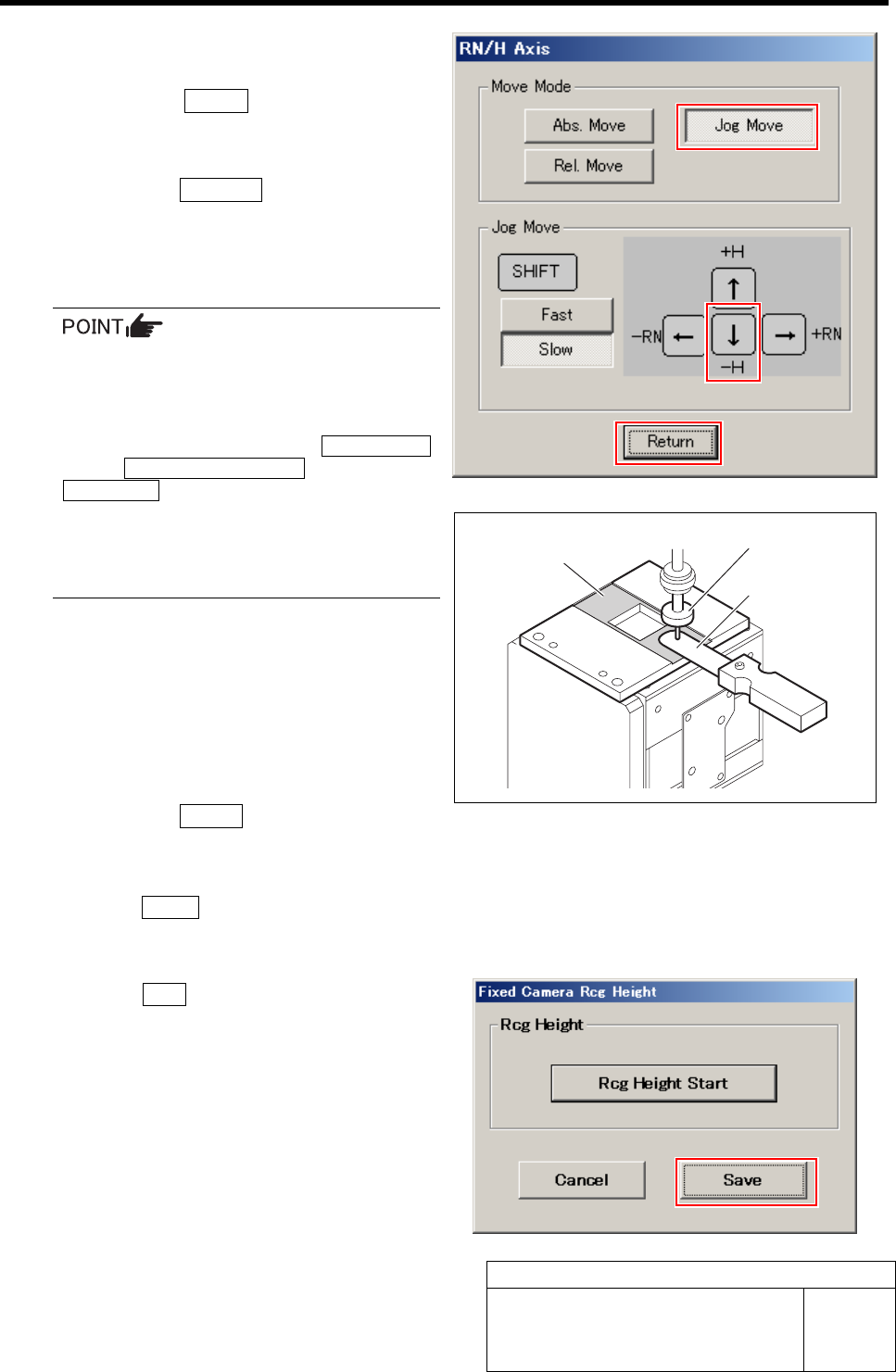
12 Adjust gap between the fixed camera jig
base and length reference nozzle jig.
1. Press the START button on the opera-
tion panel.
RN/H Axis screen is displayed.
2. Click the Jog Move button.
3. Press the downward cursor key to lower
the length reference nozzle jig to height
of 0.01mm above the fixed camera jig
base (low level difference face).
If any error occurs when lowering the
length reference nozzle jig, change the
negative values of the H axis software
limit to remedy as follows.
Click in an order of the M/C SETUP
menuÎMOTOR PARAMETER tabÎ
Axis param. tab and change the negative value
of H axis software limit from [-15.0] to [-16.0].
After fixed camera rcg height is completed, be
sure to return the value of software limit to the
original value.
4. Check the gap between the length ref-
erence nozzle jig and fixed camera jig
base (low level difference face) using
thickness gauge of 0.01mm.
5. After adjusting the gap, pull out the
thickness gauge and lower the H axis
by 0.01 mm (one click) by Low speed
Jog Move.
6. Click the Return button.
“Press [START] to display H axis move dialog”
is displayed on the message screen.
13 Press the START button on the operation panel.
The present position of H axis is obtained and returns
to the Fixed Camera Rcg Height screen.
14 Click the Save button.
The fixed camera rcg height is saved and the Fixed
Camera Rcg Height screen closes.
15 Remove the fixed camera jig base and
length reference nozzle jig.
Low level difference
face
Length reference nozzle jig
Thickness gauge