SI-F130 Manual(EN)_jpg_ Rev1.pdf - 第58页
AUX Camera Coaxial Light Calibration HLF-10308-01 AUX Camera Coaxial Light Calibration SHEET 2/2 2 Select jig No. of fixed camera light calibration jig from the list box. 3 Click the Calibration S tart button. “Install c…
AUX Camera Coaxial Light Calibration
HLF-10308-01
AUX Camera Coaxial Light
Calibration
SHEET
1/2
AUX Camera Coaxial Light Calibration
[Necessary jigs]
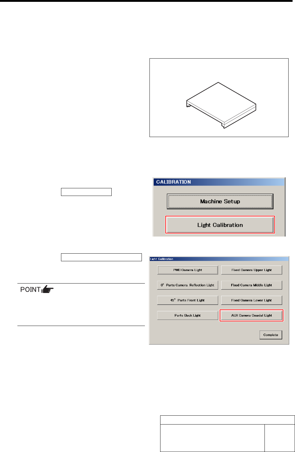
• Fixed camera light calibration jig
[Procedure]
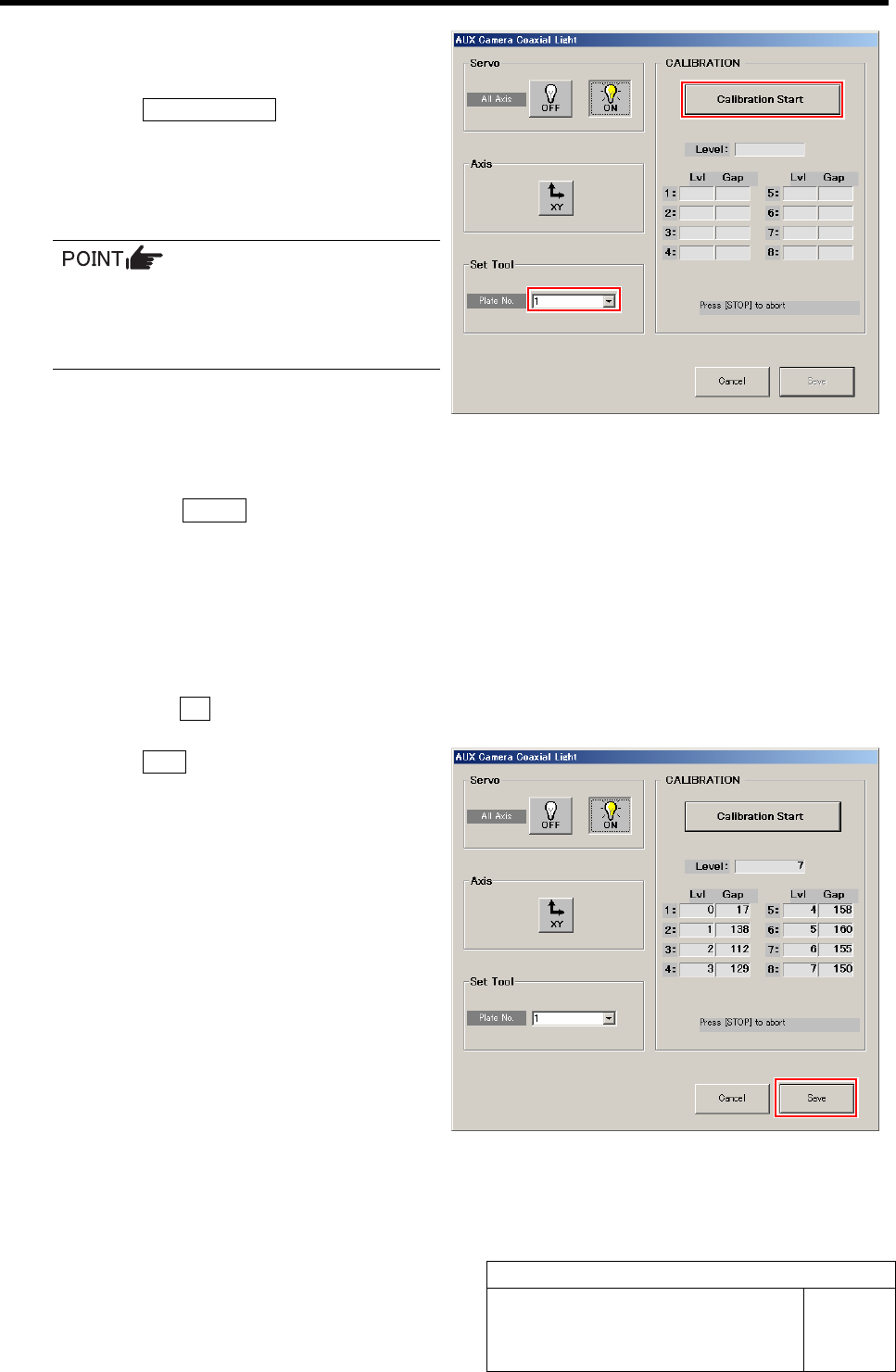
1 Display a Fixed Camera Upper Light screen.
1. Click the Light Calibration button on
the CALIBRATION screen.
Light Calibration screen is displayed.
2. Click the AUX Camera Coaxial Light
button on the Light Calibration screen.
AUX Camera Coaxial Light screen is displayed.
Each Fixed Camera Light button on the
right of the Light Calibration menu be-
comes effective in case of fixed camera
specification device.
Fixed camera light calibration jig
AUX Camera Coaxial Light Calibration
HLF-10308-01
AUX Camera Coaxial Light
Calibration
SHEET
2/2
2 Select jig No. of fixed camera light
calibration jig from the list box.
3 Click the Calibration Start button.
“Install calibration jig for fixed light. Press [START]
to start light calibration” is displayed on the message
screen.
Unless the fixed camera light calibration
jig is set, install it according to the proce-
dure 4 of the previous “Fixed Camera Up-
per Light Calibration”.
4 AUX camera coaxial light calibration is started.
1. Press the START button on the operation panel.
Calibration is started.
After a few minutes, the calibration ends, and “Remove calibration jig for fixed light” is displayed on the message
screen.
5 Remove the fixed camera light calibration jig.
1. Remove the fixed camera light calibration jig set on the fixed camera.
2. Click the OK button to close the message screen.
6 Click the Save button.
The Gap values of Lvl 1 to 8 are saved and the AUX
Camera Coaxial Light screen closes.
Parts Camera Calibration
HLF-10309-01
Parts Camera Calibration
SHEET
1/3
Parts Camera Calibration
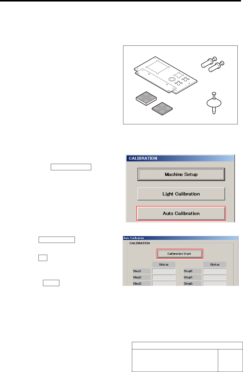
[Necessary jigs]
• Calibration plate jig
• Jig positioning pin
• Nozzle jig (AF80400)
• Jig chip (t=3.4 mm, t=1.4 mm)
[Procedure]
1 Display a Auto Calibration screen.
1. Click the Auto Calibration button on
the CALIBRATION screen.
Auto Calibration screen is displayed.
2 Click the Calibration Start button.
“Setup jig?” is displayed on the message screen.
3 Click the Yes button.
“Press [START] to move to nozzle installing position”
is displayed on the message screen.
4 Press the START button on the operation
panel.
Turrets No.1 to 4 move to the jig setup position.
Jig positioning pin
Calibration plate jig
Jig chip
(t=3.4 mm, t=1.4 mm)
Nozzle jig (AF80400)