SI-F130 Manual(EN)_jpg_ Rev1.pdf - 第49页
Parts Camera Back Light Calibration HLF-10304-01 Parts Camera Back Light Calibration SHEET 3/3 6 Press the ST ART button on the operation pane l. The turret No.1 m oves to the recognition position. 7 Re-press the ST ART …
Parts Camera Back Light Calibration
HLF-10304-01
Parts Camera Back Light Calibration
SHEET
2/3
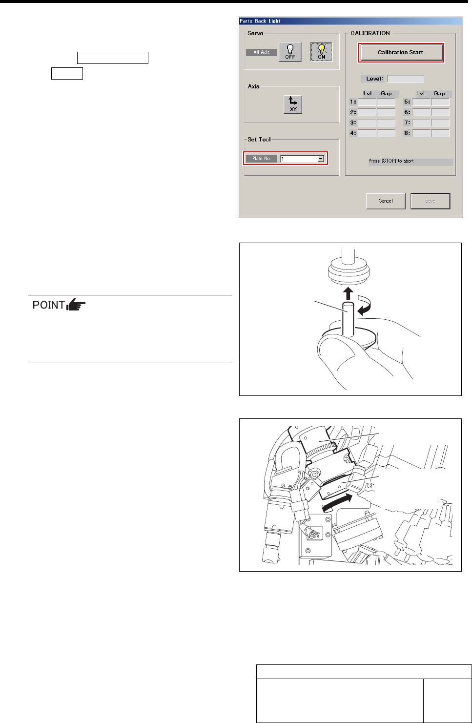
2 Select jig No. of the transmission brightness
calibration jig (filter) from the list box.
3 Click the Calibration Start button and press
the START button on the operation panel.
The turret No.1 moves to the jig setup position.
4 Install the transmission nozzle jig to the tur-
ret No.1.
When installing the nozzle, insert it while
slowly turning.
After inserting the nozzle, check that it is
not drawn out by pulling downward.
5 Install the transmission brightness calibra-
tion jig to the parts camera.
Transmission
nozzle jig
Parts Camera
Transmission
brightness
calibration jig
Parts Camera Back Light Calibration
HLF-10304-01
Parts Camera Back Light Calibration
SHEET
3/3
6 Press the START button on the operation
panel.
The turret No.1 moves to the recognition position.
7 Re-press the START button on the operation
panel.
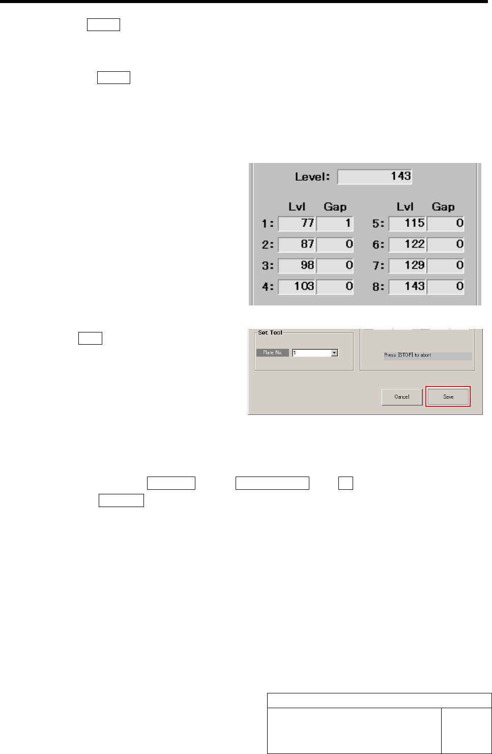
Parts camera back light calibration is started.
After a few minutes, the calibration ends, and Lv1
values from level 1 to 8 and Gap value are displayed
on the Parts Back Light screen.
8 Check the Gap values of Level 1 to 8.
It is normal if the Gap value is within 0 to 3.
9 Click the Save button.
The Gap values of Lvl 1 to 8 are saved and the Parts
Back Light screen closes.
10 Remove the transmission brightness calibration jig and transmission nozzle jig.
1. Close the Light Calibration screen and calibration screen.
2. Click in an order of MANUAL menuÎAXIS MOTION tabÎRT button.
3. Click the Jog Move button.
4. Jog move the turret No.1 toward you by pressing the left and right cursor keys to remove
the transmission brightness calibration jig and transmission nozzle jig.
Fixed Camera Upper Light Calibration
HLF-10305-01
Fixed Camera Upper Light
Calibration
SHEET
1/3
Fixed Camera Upper Light Calibration
[Necessary jigs]
• Fixed camera light calibration jig
[Procedure]
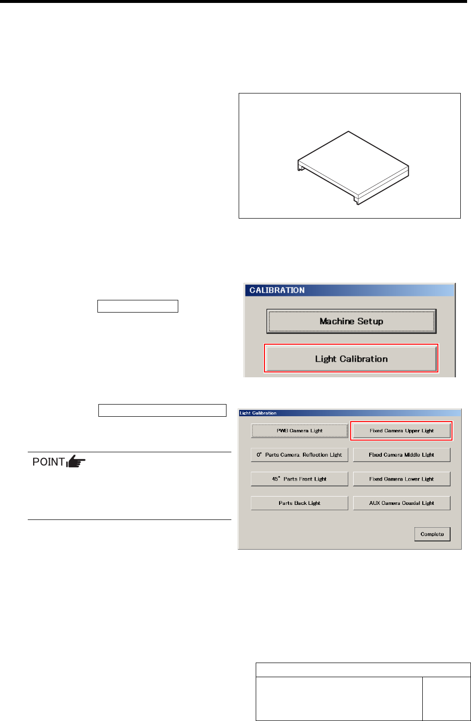
1 Display a Fixed Camera Upper Light screen.
1. Click the Light Calibration button on
the CALIBRATION screen.
Light Calibration screen is displayed.
2. Click the Fixed Camera Upper Light
button on the Light Calibration screen.
Fixed Camera Upper Light screen is displayed.
Each Fixed Camera Light button on the
right of the Light Calibration menu be-
comes effective in case of fixed camera
specification device.
Fixed camera light calibration jig