SI-F130 Manual(EN)_jpg_ Rev1.pdf - 第9页
CLF-10106-01 SI-F130 Service Manual "Console Operat ion Procedure Con- tents" SHEET 2/2 2-4 Adjustment Matching of X Axis Z- Phase ...................................................... HL F-10401-01 Matching o…
CLF-10106-01
SI-F130 Service Manual
"Console Operation Procedure Con-
tents"
SHEET
1/2
Contents
2-1 Preparation for Calibration
Install the Calibration Plate Jig..................................................HLF-10101-01
Remove Production Nozzle ......................................................HLF-10102-01
How to Display Calibration Screen ........................................... HLF-10103-01
2-2 Set-up
RT Axis Origin Position Setup...................................................HLF-10201-01
H Axis Origin Position Setup..................................................... HLF-10202-01
Acquiring Mounting Stroke Setup .............................................HLF-10203-01
PWB Camera Setup ................................................................. HLF-10204-01
Acquiring Mounting Locating Position Setup ............................ HLF-10205-01
F Axis Origin Position Setup ..................................................... HLF-10206-01
RN Axis Origin Offset Setup...................................................... HLF-10207-01
2-3 Calibration
PWB Camera Light Calibration.................................................HLF-10301-01
0 degrees Parts Camera Light Calibration................................ HLF-10302-01
45 degrees Parts Camera Light Calibration..............................HLF-10303-01
Parts Camera Back Light Calibration........................................HLF-10304-01
Fixed Camera Upper Light Calibration...................................... HLF-10305-01
Fixed Camera Middle Light Calibration..................................... HLF-10306-01
Fixed Camera Lower Light Calibration...................................... HLF-10307-01
AUX Camera Coaxial Light Calibration..................................... HLF-10308-01
Parts Camera Calibration .........................................................HLF-10309-01
Calibration Data Edit................................................................. HLF-10310-01
Pickup Camera Calibration ....................................................... HLF-10311-01
Fixed Camera Rcg Height Calibration ...................................... HLF-10312-01
Fixed Camera Calibration ......................................................... HLF-10313-01
Pickup Position Setup............................................................... HLF-10314-01
Software Limit Setup................................................................. HLF-10315-01
Conveyor Width Adjustment...................................................... HLF-10316-01

CLF-10106-01
SI-F130 Service Manual
"Console Operation Procedure Con-
tents"
SHEET
2/2
2-4 Adjustment
Matching of X Axis Z-Phase...................................................... HLF-10401-01
Matching of Y Axis Z-Phase...................................................... HLF-10402-01
H Axis Gear Z-phase Matching ................................................. HLF-10403-01
Adjustment of H Axis Upper End OT Sensor (H-CCW)............. HLF-10404-01
Adjustment of H axis Lower End OT Sensor (H-CW) ...............HLF-10405-01
FF/FR Axis Z-Phase Matching.................................................. HLF-10406-01
Adjustment of FF/FR Axis Belt Tension..................................... HLF-10407-01
Adjustment of FF/FR Axis Feed Roller Y-Direction Position...... HLF-10408-01
Adjustment of FF/FR Axis Feed Roller Height .......................... HLF-10409-01
Position Adjustment for FF/FR Axis Feeder Backward
Detect Sensor ......................................................................... HLF-10410-01
Adjustment of FF/FR Axis Feed Roller Origin Sensor Dog ....... HLF-10411-01
Adjustment of FF/FR Axis Feed Roller X-Direction Position ..... HLF-10412-01
Adjustment of RT Axis Belt Tension .......................................... HLF-10413-01
Adjustment of RN Axis Belt Tension.......................................... HLF-10414-01
Gap Adjustment for Head Unit Mechanical Valve
and Plunger ............................................................................HLF-10415-01
Adjustment of Plunger Upper/Lower
Backward Detect Sensor ........................................................HLF-10416-01
Nozzle Omission Detection Sensor Position Adjustment .......... HLF-10417-01
Phase Adjustment for Nozzle.................................................... HLF-10418-01
Adjustment of PWB Sensor ...................................................... HLF-10419-01
Adjustment of Cassette Float Sensor Height ............................ HLF-10420-01
Adjustment of PWB Stopper Sensor ......................................... HLF-10421-01
Fixed Camera Parts Presence / Absence Sensor Setup ..........HLF-10422-01
Ejector Setup ............................................................................ HLF-10423-01
Adjustment of Bulk Unit Position............................................... HLF-10424-01
Blow Flow rate Setup................................................................ HLF-10425-01
Supplied Air Sensor Setup........................................................ HLF-10426-01
Vacuum Sensor Setup .............................................................. HLF-10427-01
Install the Calibration Plate Jig
HLF-10101-01
Install the Calibration Plate Jig
SHEET
1/3
Install the Calibration Plate Jig
Operations to use the calibration plate jig are as follows.
When performing the following operations, install the calibration plate jig according to the proce-
dure described in this section.
Set-Up
• RT Axis Origin Position Setup
• Acquiring Mounting Stroke Setup
• PWB Camera Setup
• Acquiring Mounting Locating Position Setup
Calibration
• PWB Camera Light Calibration
• Parts Camera Calibration
• Pickup Camera Calibration
• Fixed Camera Calibration
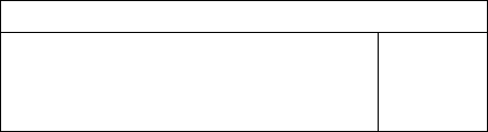
[Necessary jigs]
A Calibration plate jig
B Jig positioning pin
[Procedure]
1 Press the emergency stop switch to turn off the servo.
2 Turn off the interlock switch and open the front door.
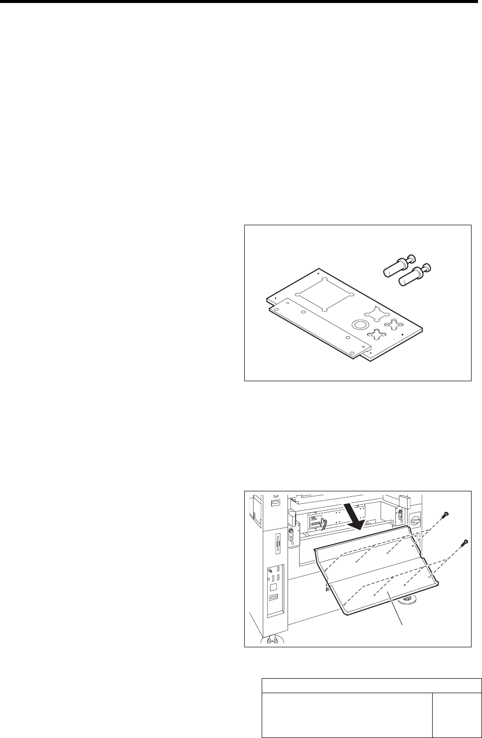
3 Unscrew the 8 screws and remove the
shooter on the front side of the unit.
B
A
Shooter