SI-F130 Manual(EN)_jpg_ Rev1.pdf - 第46页
45 degrees Parts Camera Light Calibratio n HLF-10303-01 45 degrees Parts Camera Light Calibration SHEET 2/2 5 Press the ST ART button on the operation pane l. The turret No.1 m oves to the recognition position. 6 Check t…
45 degrees Parts Camera Light Calibration
HLF-10303-01
45 degrees Parts Camera Light
Calibration
SHEET
1/2
45 degrees Parts Camera Light Calibration
[Necessary jigs]
• Light Calibration jig
• Nozzle jig (AF80400)
[Procedure]
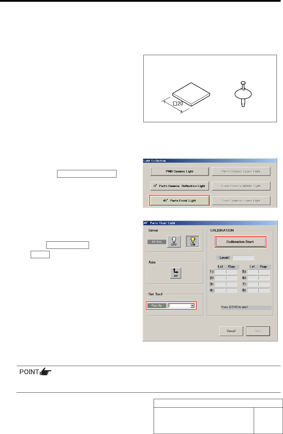
1 Display a 45° Parts Front Light screen.
1. Click the 45° Parts Front Light button
on the Light Calibration screen.
45° Parts Front Light screen is displayed.
2 Select jig No. of light calibration jig from the
list box.
3 Click the Calibration Start button and press
the START button on the operation panel.
The turret No.1 moves to the jig setup position.
4 Check that the nozzle jig (AF80400) and light calibration jig are installed.
Unless the jig is installed, install according to the procedure 4 to 5 in the previous “0 degrees
Parts Camera Light Calibration”.
Nozzle jig
(AF80400)
Light Calibration jig
45 degrees Parts Camera Light Calibration
HLF-10303-01
45 degrees Parts Camera Light
Calibration
SHEET
2/2
5 Press the START button on the operation
panel.
The turret No.1 moves to the recognition position.
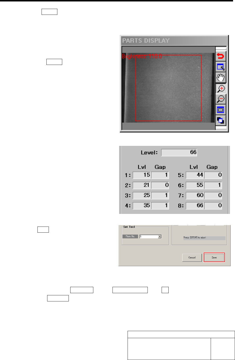
6 Check the position if the Light Calibration jig
is within the recognition range of the PARTS
DISPLAY.
7 Re-press the START button on the operation
panel.
45 degrees parts camera light calibration is started.
After a few minutes, the calibration ends, and Lv1
values from level 1 to 8 and Gap value are displayed
on the 45° Parts Front Light screen.
8 Check the Gap values of Level 1 to 8.
It is normal if the Gap value is within 0 to 3.
9 Click the Save button.
The Gap values of Lvl 1 to 8 are saved and the 45°
Parts Front Light screen closes.
10 Remove the light calibration jig and nozzle jig (AF80400).
1. Close the Light Calibration screen and calibration screen.
2. Click in an order of MANUAL menuÎAXIS MOTION tabÎRT button.
3. Click the Jog Move button.
4. Jog move the turret No.1 toward you by pressing the left and right cursor keys to remove
the light calibration jig and nozzle jig (AF80400).
Parts Camera Back Light Calibration
HLF-10304-01
Parts Camera Back Light Calibration
SHEET
1/3
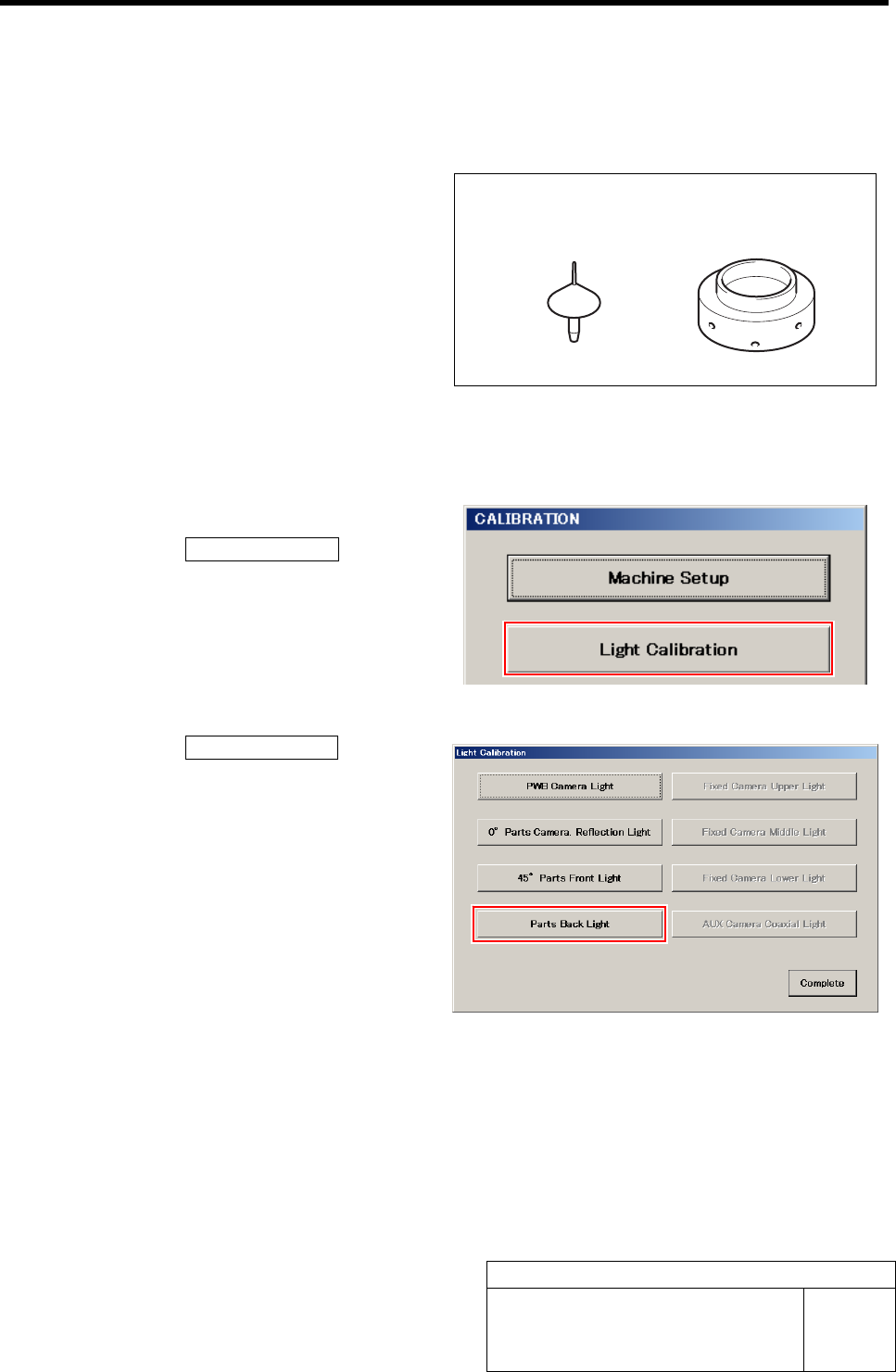
Parts Camera Back Light Calibration
[Necessary jigs]
• Transmission nozzle jig
• Transmission brightness calibration jig
[Procedure]
1 Display a Parts Back Light screen.
1. Click the Light Calibration button on
the CALIBRATION screen.
Light Calibration screen is displayed.
2. Click the Parts Back Light button on
the Light Calibration screen.
Parts Back Light screen is displayed.
Transmission brightness
calibration jig
Transmission
nozzle jig