SI-F130 Manual(EN)_jpg_ Rev1.pdf - 第110页
FF/FR Axis Z-Phase M atching HLF-10406-01 FF/FR A xis Z-Phase Match ing SHEET 1/3 FF/FR Axis Z-Phase Matching [Necessary jigs] • Do not use jig. [Procedure] 1 Loosen the cap screws (3-M4) on the F axis motor mounting bra…
Adjustment of H Axis Lower End OT Sensor (H-CW)
HLF-10405-01
Adjustment of H Axis Lower End OT
Sensor (H-CW)
SHEET
2/2
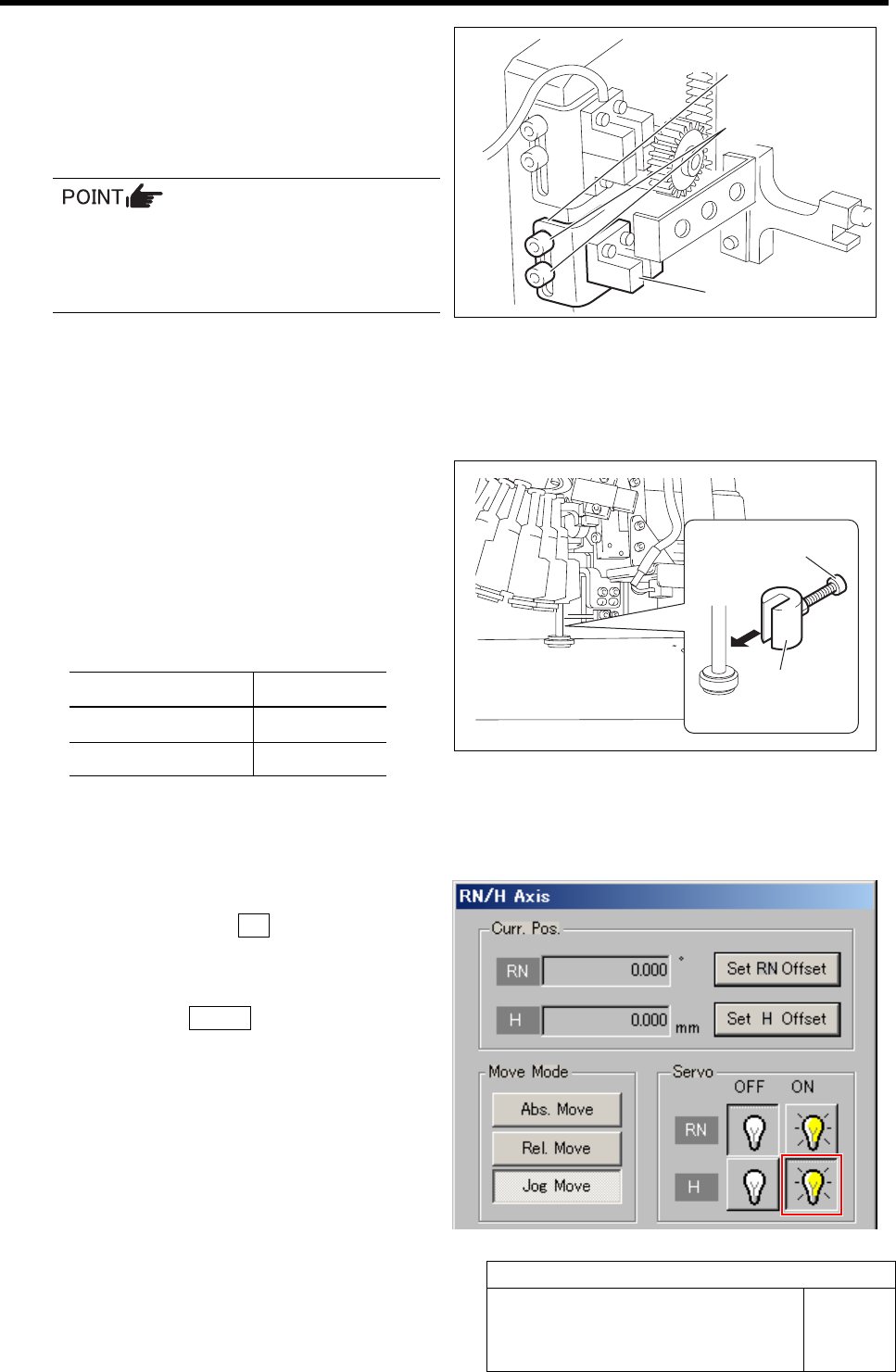
4 Loosen the cap screws (2-M3) on sensor
bracket for the H axis lower end OT sensor
to move the bracket downward (to lower
end).
The LED for H axis lower end OT sensor lights up.
• Keep the cap screws (2-M3) in temporar-
ily tightened state.
• When the H axis lower end OT sensor is
obstructed, the LED lights up.
5 Move the sensor bracket for the H axis lower end OT sensor upward little by little, tighten the cap
screws (2-M3) at a position of boundary where the lighting LED extinguishes, and secure the sensor
bracket.
6 Change the H axis sensor adjusting jig in-
stalled on the inner shaft of the turret No.1 to
a jig of 15.0 mm.
7 Check that the lighting LED for the H axis
lower end OT sensor extinguishes at this time.
Sensor setting: Dark ON
Jig used State of LED
Jig 1 (L = 15.5 mm) Lights-up
Jig 2 (L = 15.0 mm) Extinguish
8 When raising and lowering the dog for the H axis sensor, check that the H axis upper end OT sensor
does not interfere with the ORG sensor cable.
9 Return the H axis servo back to on.
1. Click the servo ON button for H axis
on the RN/H Axis screen.
Servo for H axis is turned on.
2. Click the Return button to close the
RN/H Axis screen.
Sensor bracket
Cap screw
H axis lower end OT sensor
H axis sensor
adjusting jig
Cap screw
FF/FR Axis Z-Phase Matching
HLF-10406-01
FF/FR Axis Z-Phase Matching
SHEET
1/3
FF/FR Axis Z-Phase Matching
[Necessary jigs]
• Do not use jig.
[Procedure]
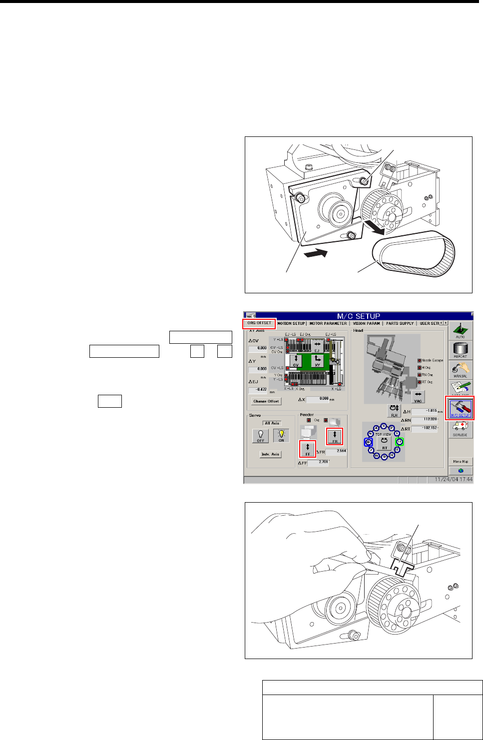
1 Loosen the cap screws (3-M4) on the F axis
motor mounting bracket.
2 Slide the bracket to the driven gear side to
remove the belt.
Temporarily fasten the cap screws for the
bracket.
3 Return the F axis to origin.
1. Click in an order of M/C SETUP
menuÎORG OFFSET tabÎFF / FR
button.
FF Axis or FR Axis screen is displayed.
2. Press the ORG button on the operation
panel with the FF Axis or FR Axis
screen being displayed
FF axis or FR axis returns to origin.
4 When the motor pulley starts to idle to return
to origin, obstruct the origin sensor with pa-
per.
The motor pulley slowly stoops with Z-phase after a
few seconds.
Cap screw
Bracket
Belt
Origin sensor
FF/FR Axis Z-Phase Matching
HLF-10406-01
FF/FR Axis Z-Phase Matching
SHEET
2/3
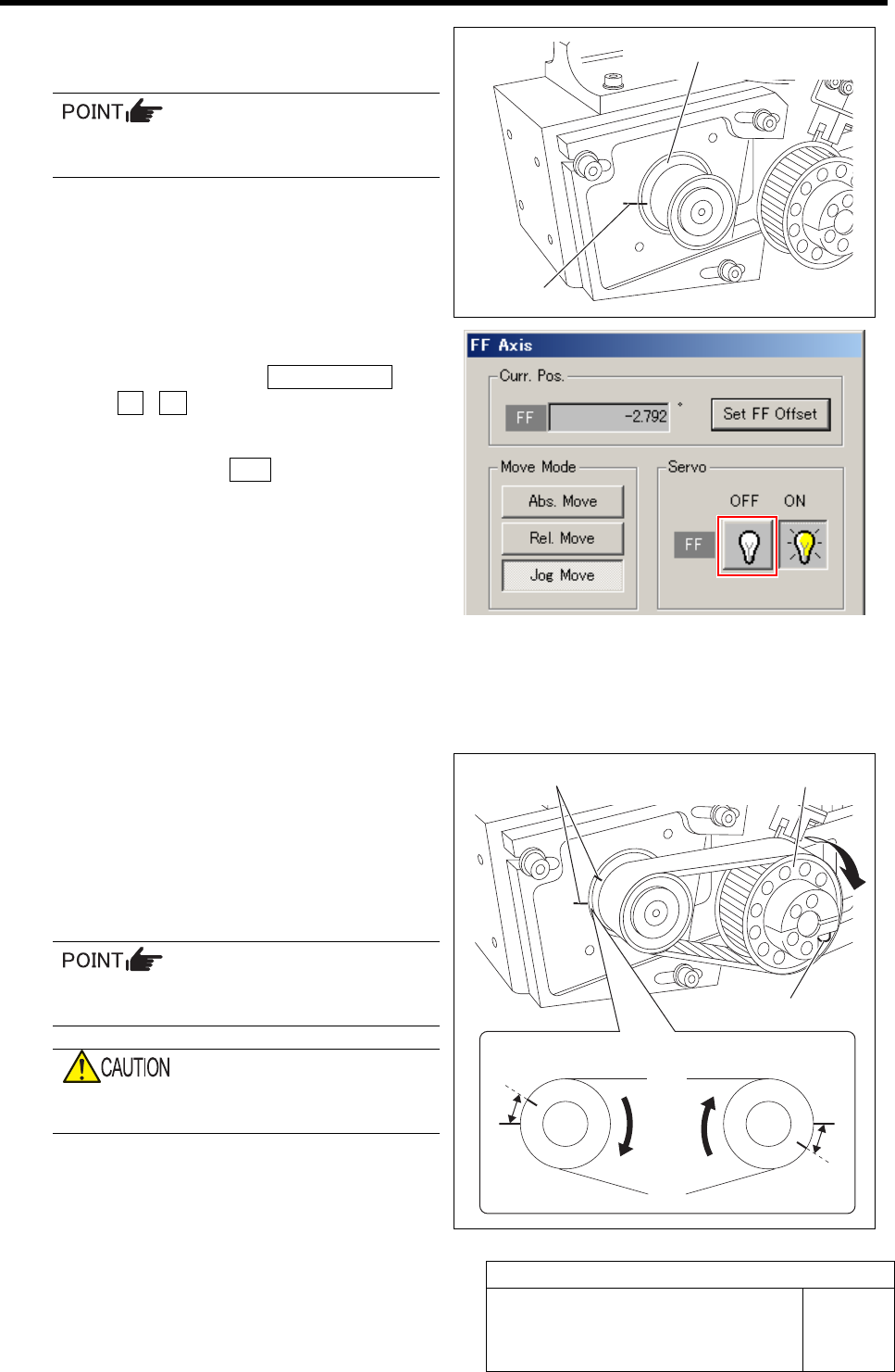
5 Draw marking off line on the motor pulley
and feed body main body.
Apply a marking off line to be as thin as
possible.
6 Turn OFF the servo for FF axis or FR axis.
1. Click in an order of ORG OFFSET tab
ÎFF / FR button.
FF Axis or FR Axis screen is displayed.
2. Click the servo OFF button for FF axis
or FR axis.
Servo for FF axis or FR axis is turned off.
7 Apply the belt to both gears.
The marking off lines on both the motor pulley and
the feed body should come to each other as close as
possible.
8 Loosen the split fastening screw of the
driven gear to make the pulley free.
9 Turn the free driven pulley clockwise to ad-
just the interval of the marking off lines on
the motor pulley and the feed body to
2.0±0.5 mm.
At this time, push up the roller to adhere it
to the cam follower beforehand.
When turning the driven gear, be careful not
to turn the axis together.
Marking off line
Motor pulley
Marking off line
Driven pulley
Split fastening screw
A
FF axis FR axis
A
A=2.0±0.5 mm