SI-F130 Manual(EN)_jpg_ Rev1.pdf - 第39页
PWB Camera Light Calibrat ion HLF-10301-01 PWB Camera Light Calibration SHEET 1/3 PWB Camera Light Calibration [Necessary jigs] • Calibration plate jig • Jig positioning pin • Light Calibration jig [Procedure] 1 Display …
RN Axis Origin Offset Setup
HLF-10207-01
RN Axis Origin Offset Setup SHEET
3/3
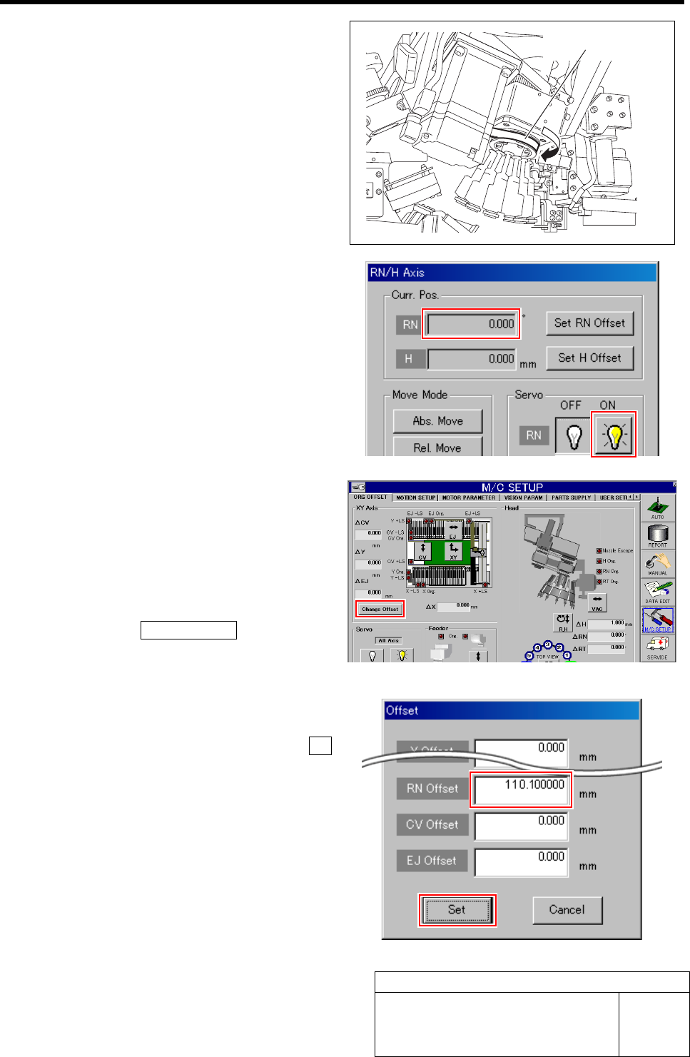
5 Check the rotating angle when rotating the
RN axis belt counterclockwise.
1. Turn on the servo for the RN axis at a
position where the RN axis is rotated
counterclockwise and stops.
2. Take note of angle of the RN axis dis-
played on the RN/H Axis screen.
(Example: -149.5˚)
6 Set a half of the value for which the angle
when rotated clockwise and the angle when
rotated counterclockwise are added as a RN
axis offset value.
1. Calculate the offset value of the RN axis.
Example: (369.7 + (-149.5)) / 2 = 110.1
2. Click the Change Offset button on the
ORG OFFSET screen.
Offset screen is displayed.
3. Input the value (example: 110.1) ob-
tained in the previous procedure into
the RN Offset box, and click the Set
button.
RN offset value is set.
RN axis belt
PWB Camera Light Calibration
HLF-10301-01
PWB Camera Light Calibration
SHEET
1/3
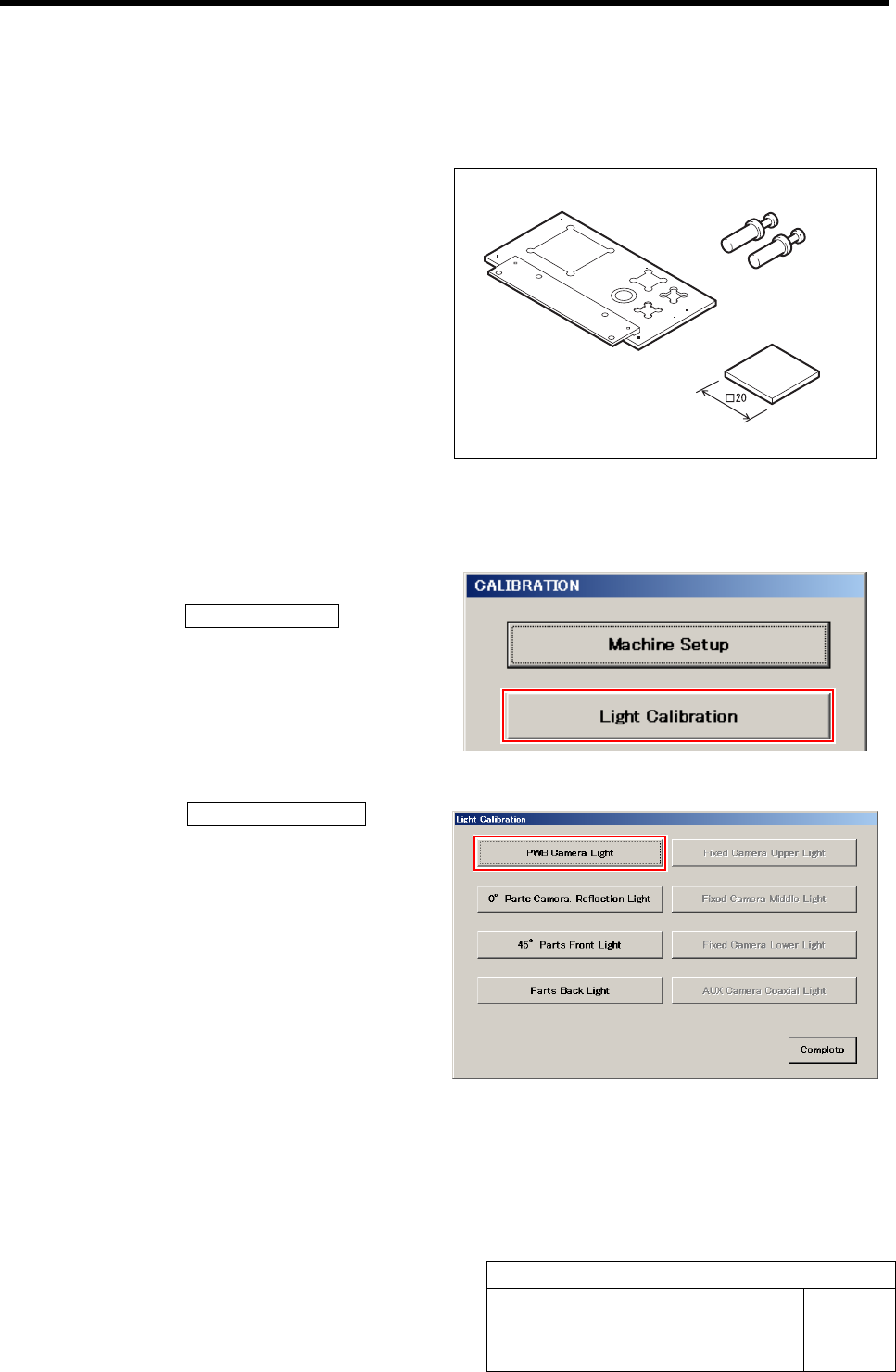
PWB Camera Light Calibration
[Necessary jigs]
• Calibration plate jig
• Jig positioning pin
• Light Calibration jig
[Procedure]
1 Display the PWB Camera Light screen.
1. Click the Light Calibration button on
the CALIBRATION screen.
Light Calibration screen is displayed.
2. Click the PWB Camera Light button
on the Light Calibration screen.
PWB Camera Light screen is displayed.
Jig positioning pin
Calibration plate jig
Light Calibration jig
PWB Camera Light Calibration
HLF-10301-01
PWB Camera Light Calibration
SHEET
2/3
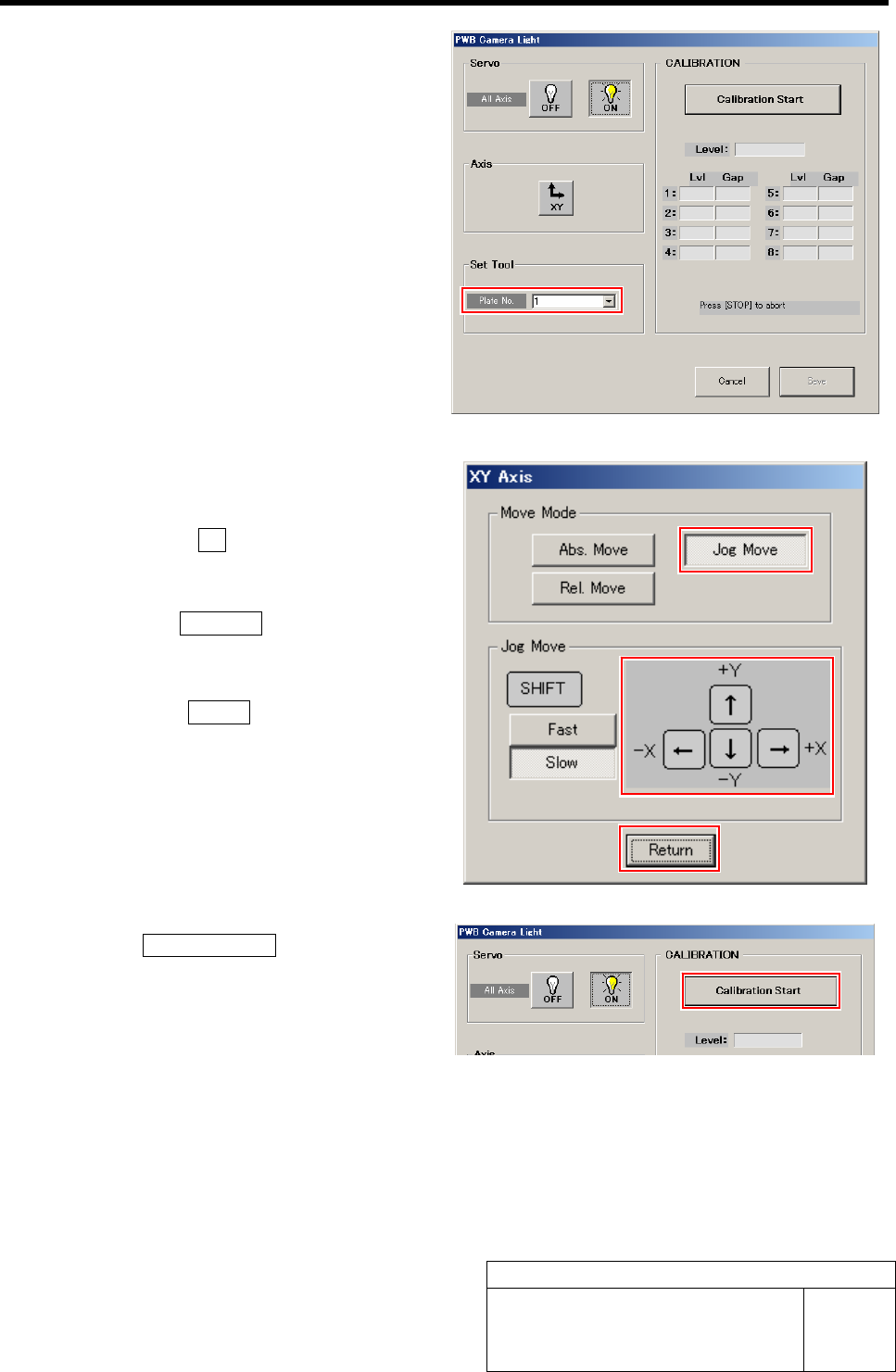
2 Select jig No. of light calibration jig from the
list box.
3 Move the PWB camera to above the calibra-
tion plate jig.
1. Click the XY button on the PWB
Camera Light screen.
XY Axis screen is displayed.
2. Click the Jog Move button.
3. Jog move the PWB camera to above
the calibration plate jig.
4. Click the Return button to return to
the PWB Camera Light screen.
4 Click the Calibration Start button.
“Put jig under PWB camera” is displayed on the mes-
sage screen.