SI-F130 Manual(EN)_jpg_ Rev1.pdf - 第104页
H Axis Gear Z-phase Matching HLF-10403-01 H A xis Gear Z-phase Matchi ng SHEET 4/4 11 Check that the clearance betwee n the H axis pus her and inner shaft is 1.0 mm by thickness g auge. Unless the clearance is 1.0 mm, it…
H Axis Gear Z-phase Matching
HLF-10403-01
H Axis Gear Z-phase Matching
SHEET
3/4
7 Check that the motor shaft is idling while
origin position return is performed, once
escape the dog for H axis sensor from the
ORG sensor.
The motor shaft slowly stops in Z-phase after a few
seconds.
Unless the gear is free against the motor
shaft of the H axis, the dog obstructs the
CCW sensor and the servo is turned off.
Check that the gear is completely free
against the motor shaft of the H axis.
8 Check if the inner shaft lowers by pushing
upward.
9 Adjust the clearance between the H axis
pusher and inner shaft end to 1.0 mm, and
secure the H axis motor gear by split fas-
tening screw.
Be careful to prevent hand from being caught
because of work with servo ON.
1. Insert a thickness gauge of 1.0 mm
into the clearance between the H axis
pusher and inner shaft end.
2. Tighten the split fastening screw for
the H axis motor gear.
3. Remove the thickness gauge.
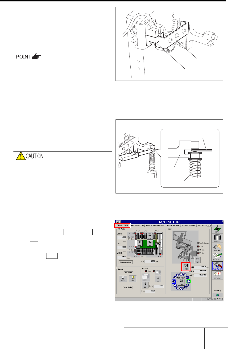
10 Perform origin position return for H axis only.
1. Click in an order of ORG OFFSET tab
ÎR.H button.
RN/H Axis screen is displayed.
2. Press the ORG button on the operation
panel with the RN/H Axis screen being
displayed.
Origin position return is performed for the H axis
only.
Dog
ORG sensor
Thickness gauge
H axis pusher
Inner shaft
H Axis Gear Z-phase Matching
HLF-10403-01
H Axis Gear Z-phase Matching
SHEET
4/4
11 Check that the clearance between the H axis pusher and inner shaft is 1.0 mm by thickness gauge.
Unless the clearance is 1.0 mm, it is necessary to re-perform “H axis origin position setup”.
12 Install the H axis lower end sensor (H-CW).
Perform position adjustment of the lower end sensor (H-CW) in the post-process of “Adjustment
H axis lower end OT sensor (H-CW)”.
13 Return the servo parameter of the H axis to the previous value.
Return the H axis parameter changed in the procedure 5 to the previous value and click the Set button.
Adjustment of H Axis Upper End OT Sensor (H-CCW)
HLF-10404-01
Adjustment of H Axis Upper End OT
Sensor (H-CCW)
SHEET
1/3
Adjustment of H Axis Upper End OT Sensor (H-CCW)
[Necessary jigs]
• H axis sensor adjusting jig
(L=15.5 mm, 15.0 mm)
• Thickness gauge (t=1.6 mm)
[Procedure]
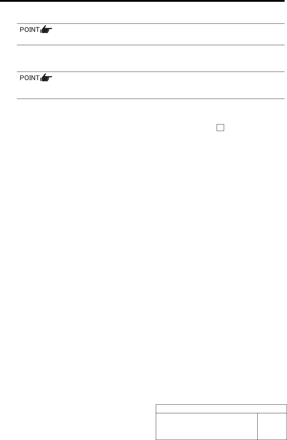
1 Install the H axis sensor adjusting jig to the
inner shafts of turrets No.2 and No.12.
1. Push down the inner shaft of the tur-
ret No.2 and pinch the H axis sensor
adjusting jig (L=15.5 mm) between the
turret and inner shaft.
2. Push down the inner shaft of the tur-
ret No.12 and pinch the H axis sensor
adjusting jig (L=15.5 mm) between the
turret and inner shaft.
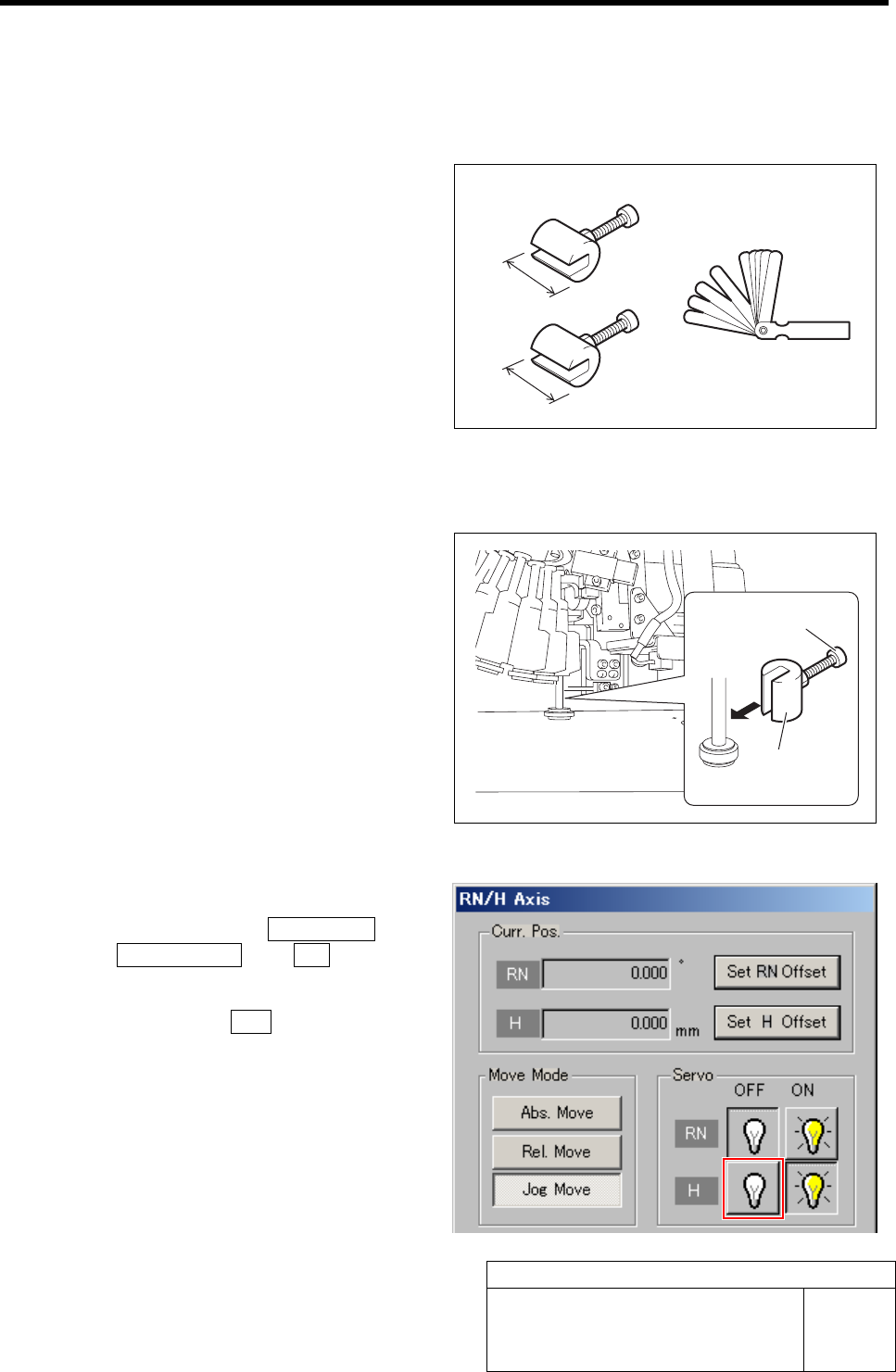
3. Remove the cap screw for H axis sen-
sor adjusting jig.
2 Turn off the servo for H axis.
1. Click in an order of M/C SETUP menu
ÎORG OFFSET tabÎR.H button.
RN/H Axis screen is displayed.
2. Click the servo OFF button for H axis.
Servo for H axis is turned off.
H axis sensor adjusting jig
15.5 mm
15 mm
H axis sensor
adjusting jig
Cap screw
Thickness gauge