SI-F130 Manual(EN)_jpg_ Rev1.pdf - 第82页
Pickup Position Setup HLF-10314-01 Pickup Position Setup SHEET 4/7 2. Click the Set the crosshair to t he white ball center button. 3. Press the ST ART button on the opera- tion panel. The PWB camera aut omatically moves…
Pickup Position Setup
HLF-10314-01
Pickup Position Setup
SHEET
3/7
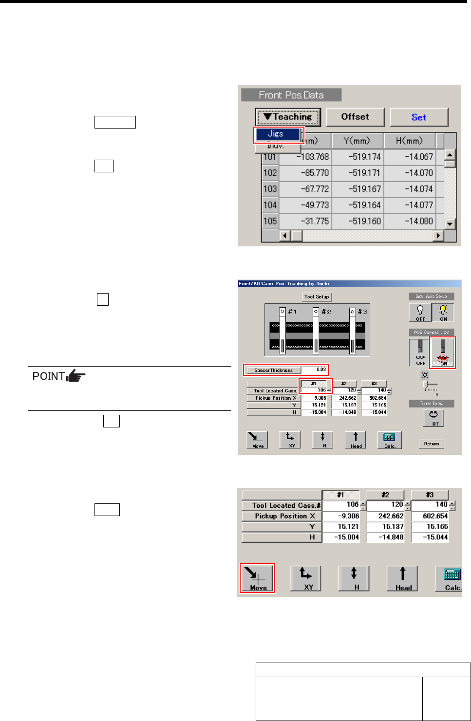
XY Position Data Teaching
[Procedure]
1 Display a Front/All Cass. Pos. Teaching by
Tools screen.
1. Click the Teaching button on the Front
Pos. Data to display a drop down
menu.
2. Click the Jigs in the drop down menu.
The Front/All Cass. Pos. Teaching by Tools
screen is displayed.
2 Set the jig.
1. Click the #1 and input “106” in input
box for Tool Located Cass.
2. Input thickness of “0.03” of thickness
gauge used for H axis position data
teaching.
The value of the spacer thickness becomes
offset value when acquiring H coordinate.
3. Click the ON button on the PWB
camera light.
The PWB camera light lights up.
3 Move the PWB camera to the pickup point.
1. Click the Move button.
Move screen is displayed.
Pickup Position Setup
HLF-10314-01
Pickup Position Setup
SHEET
4/7
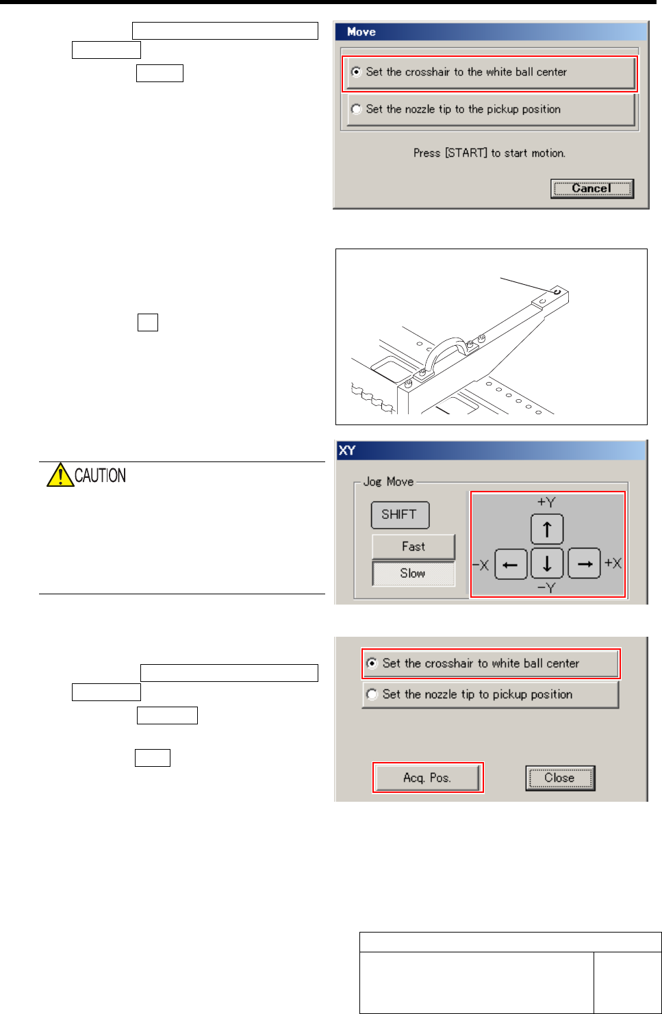
2. Click the Set the crosshair to the white
ball center button.
3. Press the START button on the opera-
tion panel.
The PWB camera automatically moves to nearly
the center of the pickup point.
4 Adjust XY position of the pickup point by jog
move while checking on the PARTS
DISPLAY.
1. Click the XY button on the Front/All
Cass. Pos. Teaching by Tools screen.
XY screen is displayed.
2. Press the cursor key to jog move the
head until the hole in the end of the
pickup point jig is positioned on the
crosshair on the PARTS DISPLAY.
When checking on the PARTS DISPLAY with
the screen being small, discrepancy of hole
center may not be found.
Be sure to expand the window of the PARTS
DISPLAY to enlarge the displayed image and
check the hole center.
5 Acquire the XY position after positioning.
1. Click the Set the crosshair to white
ball center button.
2. Click the Acq. Pos. button on the XY
screen to acquire XY position.
3. Click the Close button to close the XY
screen.
This is completion of acquiring the XY position
data of Z106.
Subsequently, perform “H Position Data Teach-
ing” at the position of Z106.
Pickup point position
Pickup Position Setup
HLF-10314-01
Pickup Position Setup
SHEET
5/7
H Position Data Teaching
[Procedure]
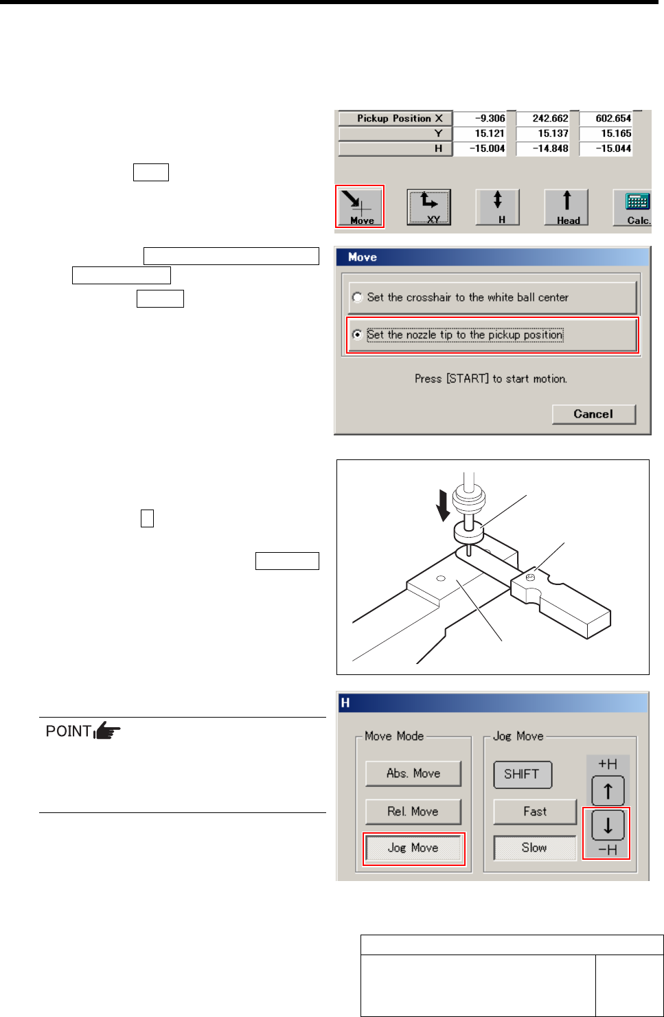
1 Move the length reference nozzle jig to the
pickup point.
1. Click the Move button on the Front/All
Cass. Pos. Teaching by Tools screen.
Move screen is displayed.
2. Click the Set the nozzle tip to the
pickup position button.
3. Press the START button on the opera-
tion panel.
Length reference nozzle jig of the turret No.1
automatically moves to the pickup point.
2 Lower the length reference nozzle jig to a
height of 0.03mm above the pickup point jig.
1. Click the H button on the Front/All
Cass. Pos. Teaching by Tools screen.
H screen is displayed.Click the Jog Move
button.
3. Press the downward cursor key to
lower the H axis until the gap between
the length reference nozzle jig and
pickup point jig becomes 0.03mm.
4. Check the gap using a thickness gauge
of 0.03mm.
• Use a thickness gauge with the same
thickness as the “spacer thickness” input
in the Front/All Cass. Pos. Teaching by
Tools screen.
Length reference
nozzle jig
Thickness gauge
Pickup point jig