SI-F130 Manual(EN)_jpg_ Rev1.pdf - 第36页
RN Axis Origin Offset Setup HLF-10207-01 RN A xis Origin Offset Setup SHEET 1/3 RN Axis Origin Of fset Setup [Necessary jig] • Do not use jig. [Procedure] 1 Set the RN of fset to “ 0 ” . 1. Click in an order of M/C SETUP…
F Axis Origin Position Setup
HLF-10206-01
F Axis Origin Position Setup
SHEET
2/2
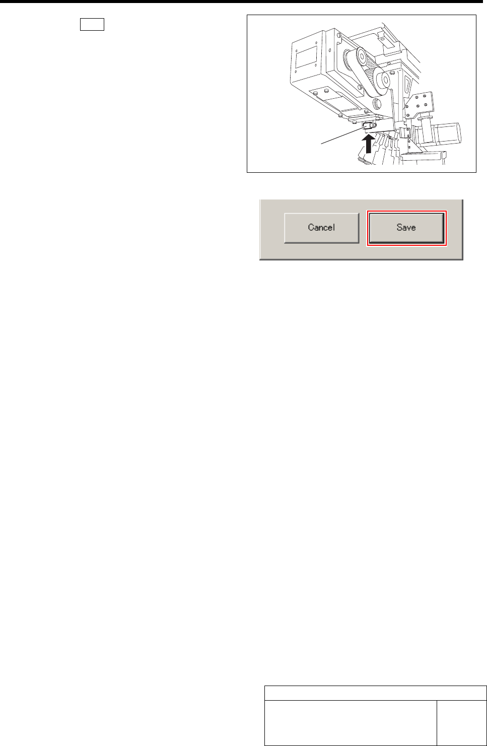
3 Click the Save button on the F Axis Home
screen with the feed roller on the front feed
body retained from the lower.
F axis origin position is saved and F Axis Home
screen closes.
Feed roller
RN Axis Origin Offset Setup
HLF-10207-01
RN Axis Origin Offset Setup SHEET
1/3
RN Axis Origin Offset Setup
[Necessary jig]
• Do not use jig.
[Procedure]
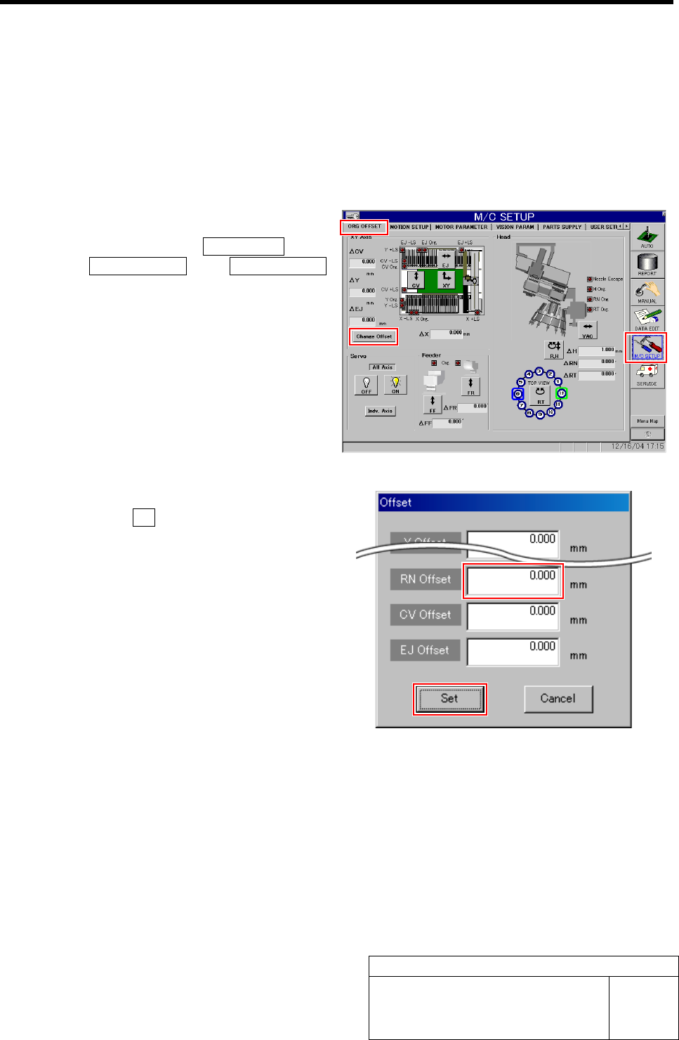
1 Set the RN offset to “0”.
1. Click in an order of M/C SETUP menu
ÎORG OFFSET tabÎChange Offset
button.
Change Offset screen is displayed.
2. Input “0” in the RN Offset box, and
click the Set button.
RN offset value is set to “0”.
RN Axis Origin Offset Setup
HLF-10207-01
RN Axis Origin Offset Setup SHEET
2/3
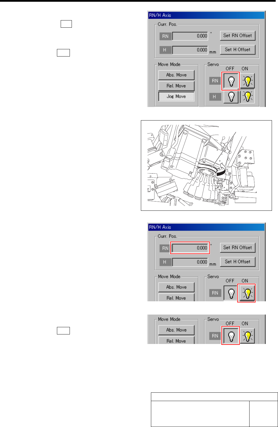
2 Turn off the servo for RN axis.
1. Click the R.H button on the ORG
OFFSET screen.
RN/H Axis screen is displayed.
2. Click the OFF button for the RN axis
servo.
3 Check the rotating angle when rotating the
RN axis belt clockwise.
1. Turn on the servo for the RN axis at a
position where the RN axis is rotated
clockwise and stops.
2. Take note of angle of the RN axis dis-
played on the RN/H Axis screen.
(Example: 369.7˚)
4 Turn off the servo for RN axis.
1. Click the OFF button for the RN axis
servo on the RN/H Axis screen.
RN axis belt