SI-F130 Manual(EN)_jpg_ Rev1.pdf - 第122页
Adjustment of FF/FR Axis Feed R oller Origin Sensor D og HLF-1041 1-01 Adjustment of FF/FR Axis Feed Roller Origin Sensor Dog SHEET 1/3 Adjustment of FF/FR Axis Fe ed Roller Origin Sensor Dog [Necessary jigs] • Feed adju…
Position Adjustment for FF/FR Axis Feeder Backward Detect Sensor
HLF-10410-01
Position Adjustment for FF/FR Axis
Feeder Backward Detect Sensor
SHEET
2/2
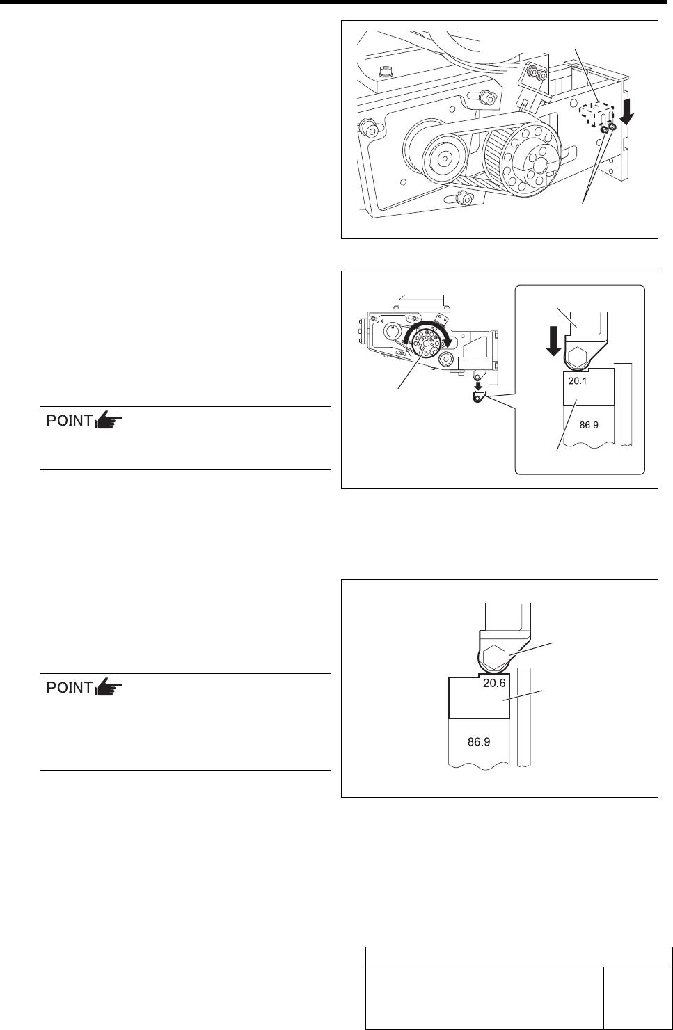
4 Loosen the cap screws (2-M2) on the feed
body to lower the PH-FFB sensor to lower
end.
5 Adjust the position of the PH-FFB sensor at
the feed roller lowest end.
1. Turn the driven pulley clockwise to
lower the feed roller.
2. Keep the feed roller contacting the F
axis return block (20.1 mm).
Turn the driven pulleys for both of the FF
axis/FR axis clockwise.
3. Move the PH-FFB sensor upward, and
fasten the cap screws (2-M2) at the
position of the boundary where the
LED in extinguished condition lights
up to fix the PH-FFB sensor.
6 Match the feed roller to the position of the
higher side (20.6 mm) of the F axis return
block, and check that the LED of the FFB
sensor extinguishes.
The LED extinguishes at the position of
higher side (20.6 mm) of the F axis return
block, and the LED lights up at the posi-
tion of lower side (20.1 mm).
7 Relocate the jig to the No.1 and 40 positions of the cassette table, and check that the LED extin-
guishes at the position of higher side (20.6 mm) of the F axis return block, and the LED lights up at
the position of lower side (20.1 mm).
Cap screw
PH-FFB sensor
Driven pulley
F axis return block
Feed roller
F axis return block
Feed roller
Adjustment of FF/FR Axis Feed Roller Origin Sensor Dog
HLF-10411-01
Adjustment of FF/FR Axis Feed
Roller Origin Sensor Dog
SHEET
1/3
Adjustment of FF/FR Axis Feed Roller Origin Sensor Dog
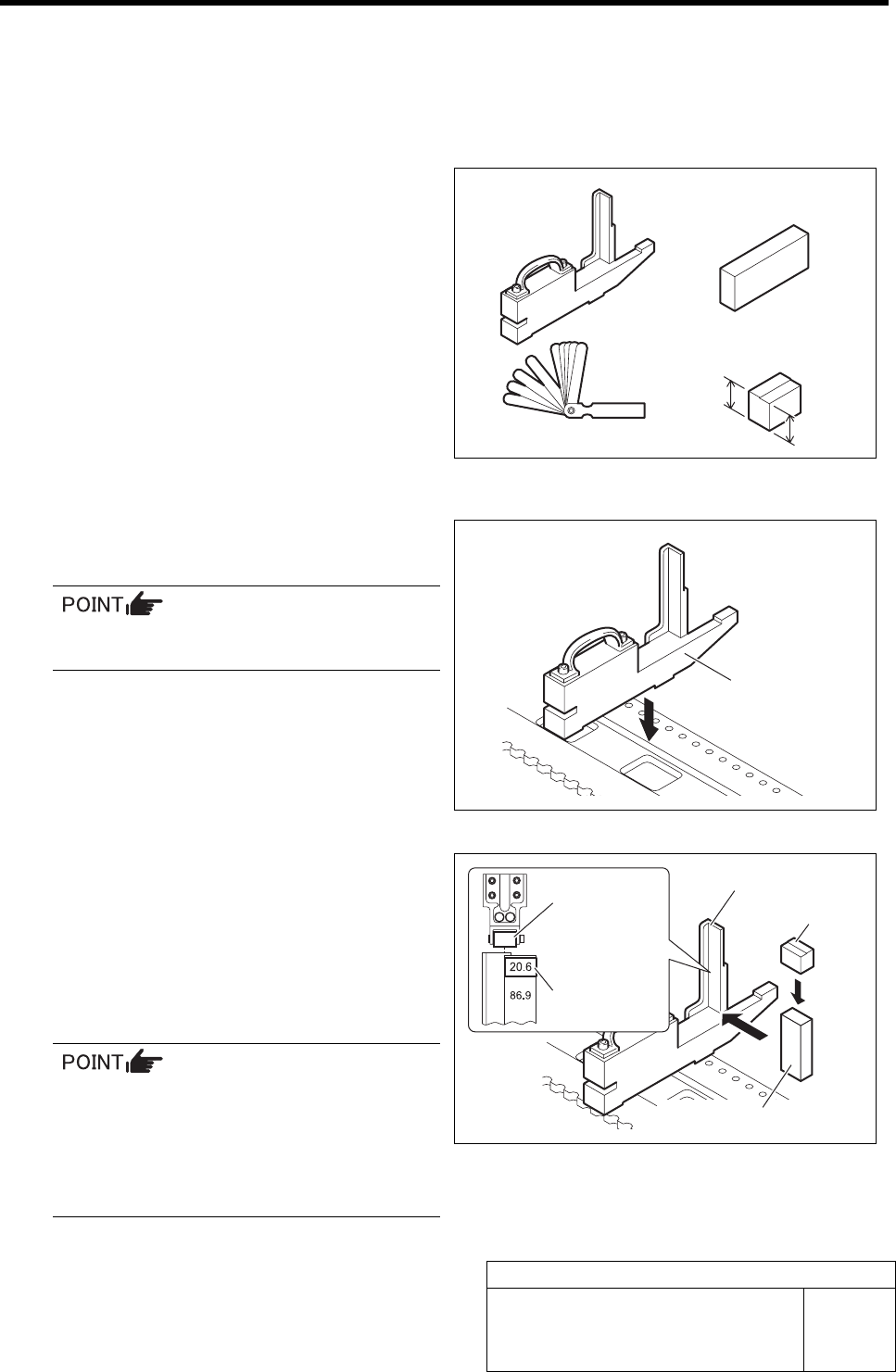
[Necessary jigs]
• Feed adjusting jig
• Part feed height jig
• F axis return block (20.6 mm, 20.1 mm)
• Thickness gauge (t=0.5 mm)
[Procedure]
1 Set the feed adjusting jig to the No.20 posi-
tion on the cassette table.
There should be no clearance between the
feed adjusting jig and the cassette table.
2 Place the part feed height jig and F axis re-
turn block on the feed adjusting jig.
3 Adjust the position so that end face of the
higher side (20.6 mm) of the F axis return
block matches with the center of the feed
roller.
The cassette feed lever is fed in the center
of the roller, however, the roller tends to be
fed in the above right direction, then, ad-
just the position of the part feed adjusting
jig between the jig end face and the roller
center.
Feed adjusting jig
Part feed height jig
F axis return block
20.6 mm
20.1 mm
Feed adjusting jig
Feed adjusting jig
Part feed height jig
Feed roller
F axis return
block
F axis return block
Thickness gauge
Adjustment of FF/FR Axis Feed Roller Origin Sensor Dog
HLF-10411-01
Adjustment of FF/FR Axis Feed
Roller Origin Sensor Dog
SHEET
2/3
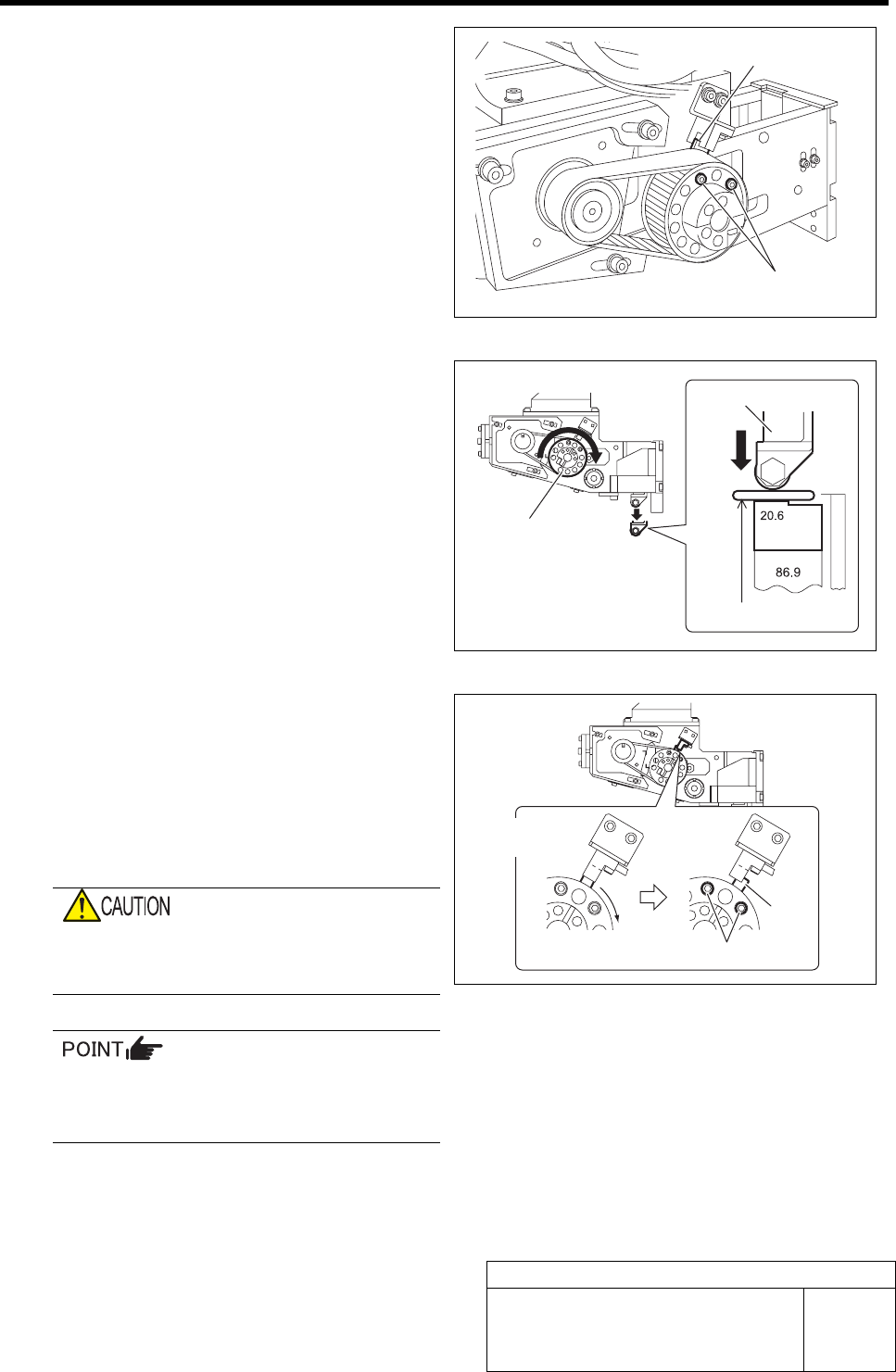
4 Loosen the cap screws (2-M3) fastening the
dog for the origin sensor.
5 Adjust the position of the dog for the origin
sensor.
1. Place a thickness gauge of t = 0.5 mm
on the F axis return block (20.6 mm).
2. Turn the driven pulley clockwise until
the feed roller contacts the thickness
gauge on the F axis block, and main-
tain this status.
3. Shield the origin sensor with the dog,
and turn off the LED.
4. Move the dog gradually, and fasten the
cap screws (2-M3) with torque of 100
cN・m at a position of boundary where
the LED in extinguished condition
lights up and fix the dog.
If the cap screw is fastened with torque
higher than specified, thread hole may be
crushed.
• Pull the dog up to the sensor side to fix.
• Turn the driven pulleys and dog for both
of the FF axis/FR axis clockwise.
Cap screw
Dog
Driven pulley
Thickness gauge
Feed roller
Extinguished
Light-up
Dog
Cap scre
w