SI-F130 Manual(EN)_jpg_ Rev1.pdf - 第126页
Adjustment of FF/FR Axis Feed R oller X-Direction Position HLF-10412-01 Adjustment of FF/FR Axis Feed Roller X-Direction Position SHEET 2/2 4 Lower the feed roller by hand to check clearance in the X dire ction with the …
Adjustment of FF/FR Axis Feed Roller X-Direction Position
HLF-10412-01
Adjustment of FF/FR Axis Feed
Roller X-Direction Position
SHEET
1/2
Adjustment of FF/FR Axis Feed Roller X-Direction Position
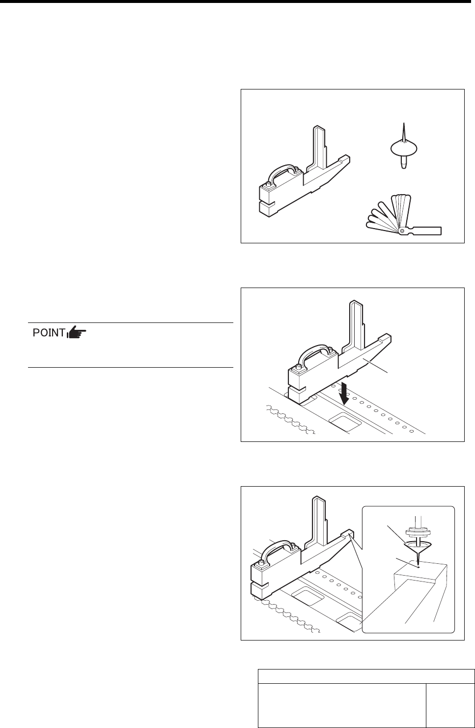
[Necessary jigs]
• Feed adjusting jig
• Nozzle jig (AF06040)
• Thickness gauge (t=1.0 mm)
[Procedure]
1 Set the feed adjusting jig to the No.20 posi-
tion on the cassette table.
There should be no clearance between the
feed adjusting jig and the cassette table.
2 Install nozzle jig (AF06040) to the turret.
3 Move the head to a position where the noz-
zle jig can be inserted into the insertion hole
of the feed adjusting jig.
Feed adjusting jig
Nozzle jig
(AF06040)
Thickness gauge
Feed adjusting jig
Nozzle jig
Insertion
hole
Adjustment of FF/FR Axis Feed Roller X-Direction Position
HLF-10412-01
Adjustment of FF/FR Axis Feed
Roller X-Direction Position
SHEET
2/2
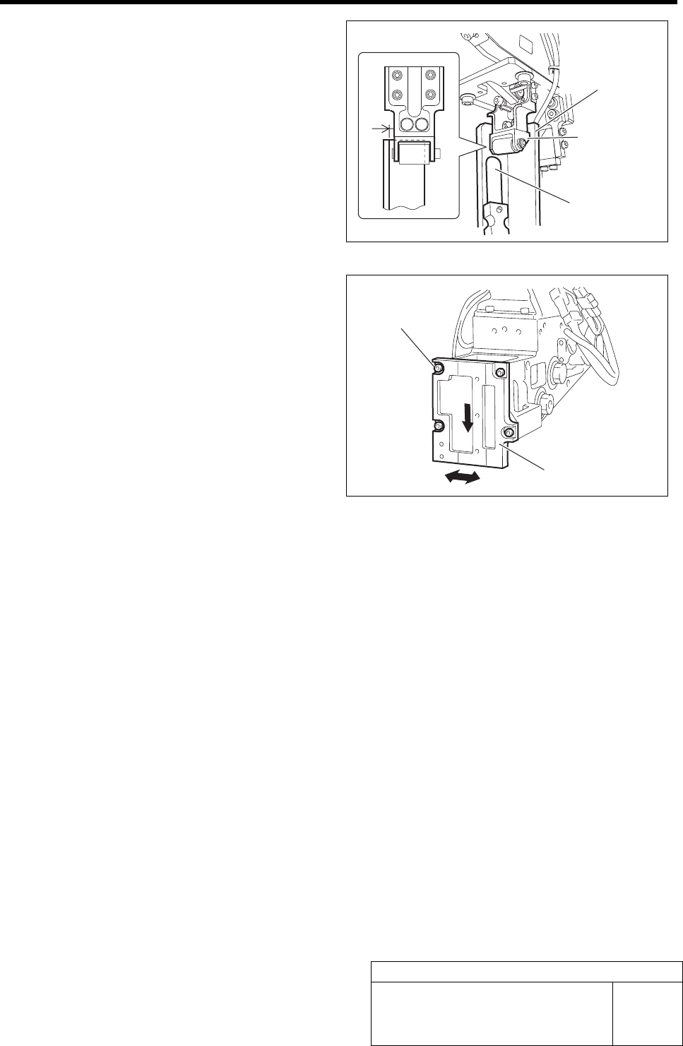
4 Lower the feed roller by hand to check
clearance in the X direction with the feed
adjusting jig.
1. Check that thickness gauge of t = 1
mm cannot be inserted into the gap in
X direction between the feed roller
bracket and the feed adjusting jig.
2. Visually check that the feed roller
bracket does not contact the feed ad-
justing jig.
5 If the clearance is out of the standard, shift
the feed roller attachment plate position to
adjust the clearance.
1. Loosen the cap screws (4-M4) on the
feed roller attachment plate.
2. Move the feed roller attachment plate
to left and right to adjust the clearance
while pushing it downward.
3. Fasten the cap screws (4-M4) at a po-
sition where the clearance is within
the standard and fix the feed roller
attachment plate.
6 After adjusting the position, recheck that the
nozzle jig can be inserted into the feed ad-
justing jig inserting hole.
Thickness gauge
Feed adjusting jig
Feed roller
bracket
Cap screw
Feed roller attachment plate
Adjustment of RT Axis Belt Tension
HLF-10413-01
Adjustment of RT Axis Belt Tension
SHEET
1/2
Adjustment of RT Axis Belt Tension
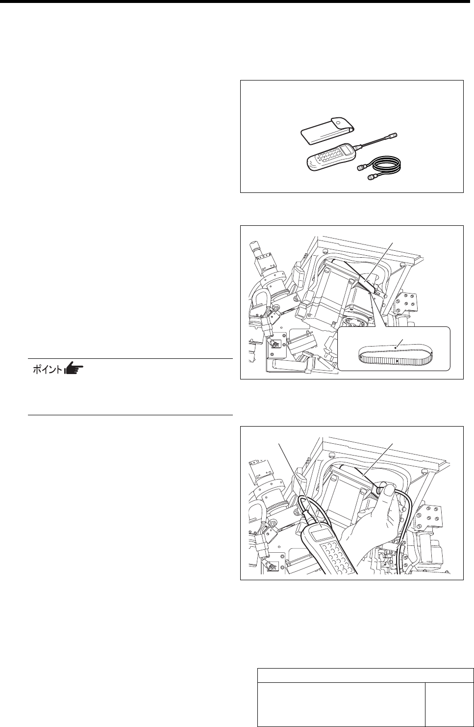
[Necessary jig]
• Tension meter
[Preparation before work]
1 Put white marking on 4 locations on the RT
axis belt in the same interval from the front
of the unit.
2 Set the tension meter.
WEIGHT : 2.5 gf/m
WIDTH : 15 mm
SPAN : 92.7 mm
MIC GAIN : Turn up the volume to a position just
before the lamp lights up.
For the detailed operating method of the
tension meter, refer to the manual at-
tached to the tension meter.
3 Measure the tension on the white marked 4
locations on the RT axis.
1. Place the measuring terminal of the
tension meter on the center between
the both pulleys.
2. Knock the RN axis belt with finger,
then tension value on the belt is dis-
played on the tension meter.
3. Measure the tension on the 4 measuring points on the RT axis belt, and check the maxi-
mum value and average value of the tension.
<Standard>
Maximum value: 7.8 kgf (76.4 N)
Average value: 7.14 to 9.18 kgf (80 ±8 N)
Tension meter
Tension meter RT axis belt
RT axis belt
White marking (4 locations)