SI-F130 Manual(EN)_jpg_ Rev1.pdf - 第65页
Pickup Camera Calibration HLF-1031 1-01 Pickup Camera Calibration SHEET 3/5 7 Press the ST ART button on the operation pane l. Length reference nozzle jig p icks up the pickup in- spection camera cal ibration jig, and me…
Pickup Camera Calibration
HLF-10311-01
Pickup Camera Calibration
SHEET
2/5
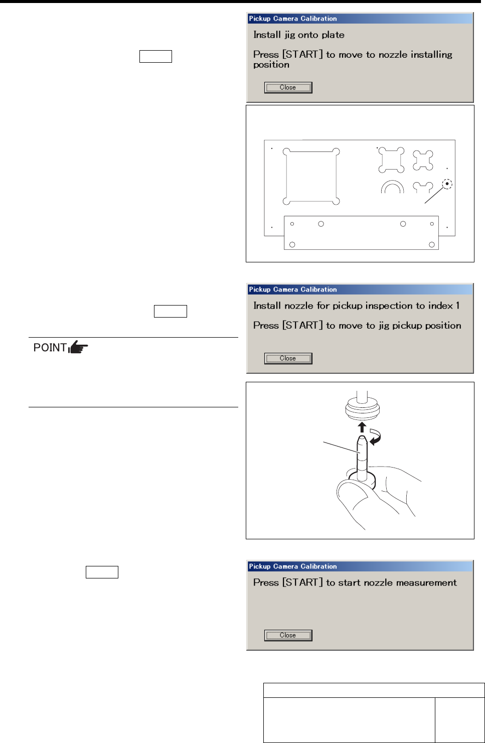
4 Set the pickup inspection camera calibration
jig into the insertion hole on the calibration
plate jig, and press the START button on the
operation panel.
Head portion moves to the jig setup position, and “In-
stall nozzle for pickup inspection to index 1” is dis-
played on the message screen.
5 Install the length reference nozzle jig to the
turret No.1 and press the START button on
the operation panel.
When installing the nozzle, insert it while
slowly turning.
After inserting the nozzle, check that it is
not drawn out by pulling downward.
The length reference nozzle jig moves to the measur-
ing position and “Press [START] to start nozzle
measurement” is displayed on the message screen.
6 Press the START button on the operation
panel.
Length reference nozzle jig measurement is per-
formed and “Press [START] to start jig measurement”
is displayed on the message screen.
Calibration plate upper surface figure
Insertion hole
Length reference
nozzle jig
Pickup Camera Calibration
HLF-10311-01
Pickup Camera Calibration
SHEET
3/5
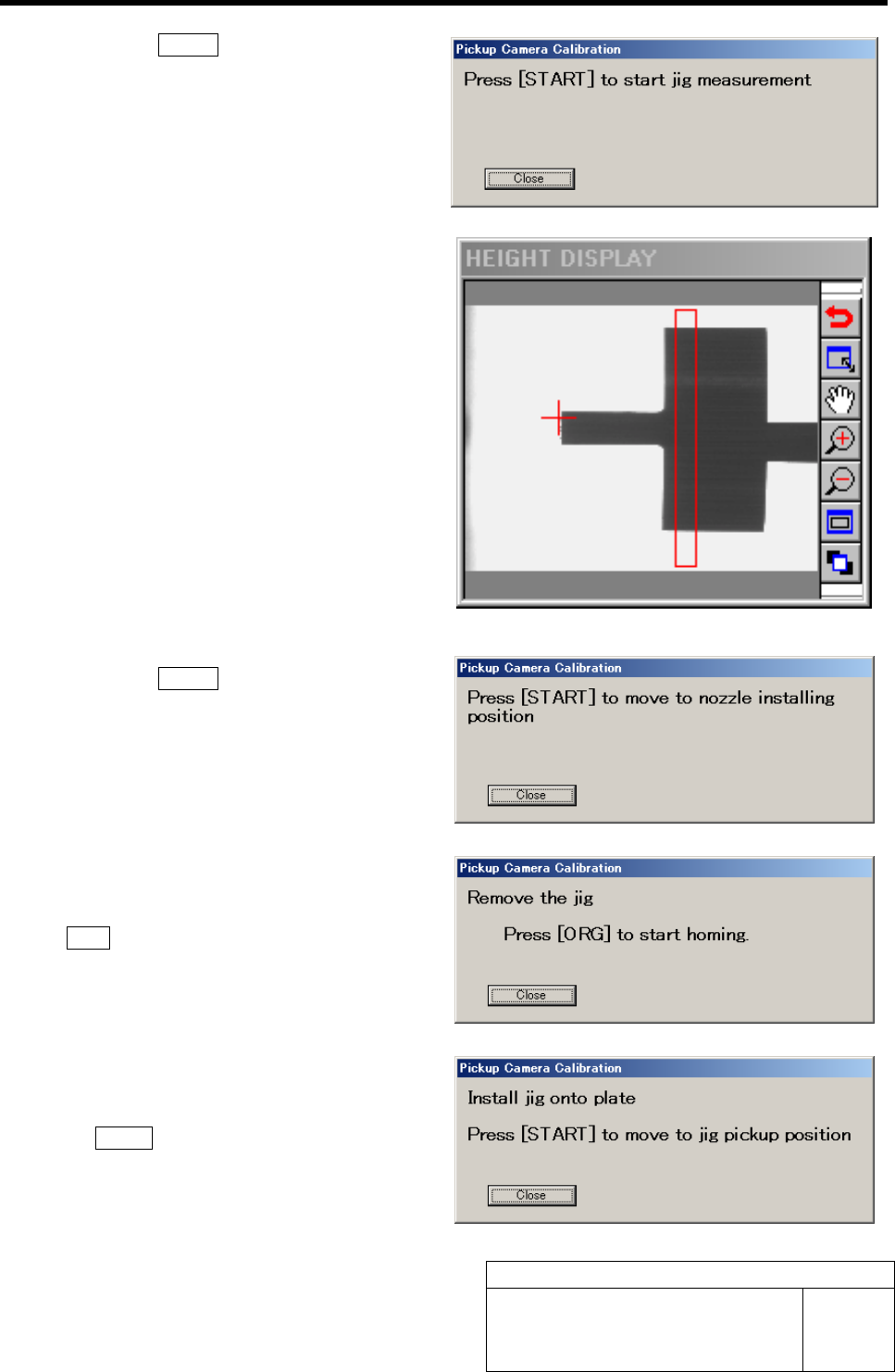
7 Press the START button on the operation
panel.
Length reference nozzle jig picks up the pickup in-
spection camera calibration jig, and measurement is
performed.
The measurement result is displayed on the HEIGHT
DISPLAY as an image.
”Press [START] to move to nozzle installing position”
is displayed on the message screen.
8 Press the START button on the operation
panel.
The turret No.1 moves to the nozzle installing position
and “Remove the jig” is displayed on the message
screen.
9 Remove the pickup inspection camera cali-
bration jig from the nozzle and press the
ORG button on the operation panel.
Origin position return is performed and “Install jig
onto plate” is displayed on the message screen.
10 Again set the pickup inspection camera calibra-
tion jig onto the calibration plate jig and press
the START button on the operation panel.
Length reference nozzle jig moves to the measuring
position and “Press [START] to start nozzle meas-
urement” is displayed on the message screen.
Pickup Camera Calibration
HLF-10311-01
Pickup Camera Calibration
SHEET
4/5
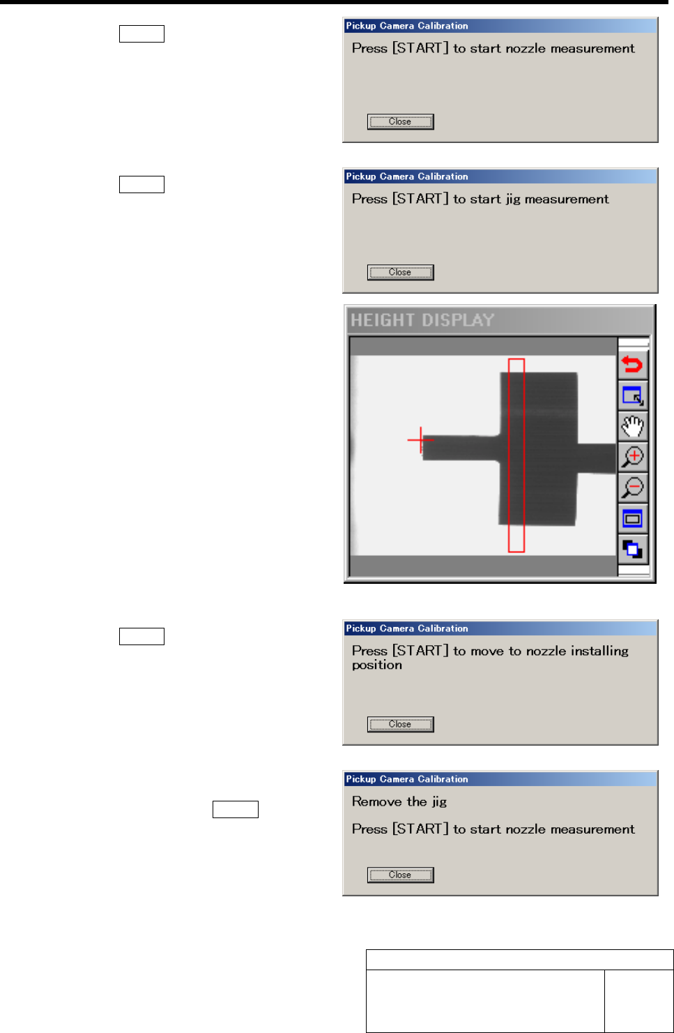
11 Press the START button on the operation
panel.
Length reference nozzle jig measurement is per-
formed and “Press [START] to start jig measurement”
is displayed on the message screen.
12 Press the START button on the operation
panel.
Length reference nozzle jig picks up the pickup in-
spection camera calibration jig, and measurement is
performed.
The measurement result is displayed on the HEIGHT
DISPLAY as an image.
”Press [START] to move to nozzle installing position”
is displayed on the message screen.
13 Press the START button on the operation
panel.
The turret No.1 moves to the nozzle installing position
and “Remove the jig” is displayed on the message
screen.
14 Remove the pickup inspection camera cali-
bration jig and press the START button on
the operation panel.
Length reference nozzle jig measurement is per-
formed and ”Press [START] to move to nozzle in-
stalling position” is displayed on the message screen.