SI-F130 Manual(EN)_jpg_ Rev1.pdf - 第125页
Adjustment of FF/FR Axis Feed R oller X-Direction Position HLF-10412-01 Adjustment of FF/FR Axis Feed Roller X-Direction Position SHEET 1/2 Adjustment of FF/FR Axis Fe ed Roller X-Direction Position [Necessary jigs] • Fe…
Adjustment of FF/FR Axis Feed Roller Origin Sensor Dog
HLF-10411-01
Adjustment of FF/FR Axis Feed
Roller Origin Sensor Dog
SHEET
3/3
6 Reset the all emergency stop switches.
7 Use PC in which Tera Term is installed to
check ORG operation.
1. Prepare PC in which Tera Term
(communication software) is installed,
and connect it to PC unit in the
equipment with cable.
2. Input the following commands with
Tera Term to check the ORG operation
three times.
-
>dacinit [Enter]
-
>dsrvon 4 [Enter](Turn ON the FF axis servo)
-
>dorg 4 [Enter](Set up origin of the FF axis)
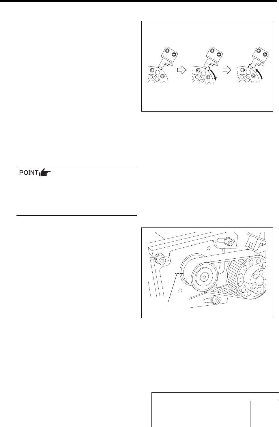
The dog rotates clockwise, leaves slightly from the
ORG sensor and again returns to the ORG sensor
(Z-phase position).
If the driven pulley makes one turn and
the feed roller lowers down, it constitutes
an adjustment error.
In this case, re-perform adjustment of feed
roller origin sensor dog.
8 Check that the marking off lines of Z-phase
drawn on the motor pulley and feed body are
coincide with each other.
Marking off line
Servo OFF
ORG Z-Phase
Adjustment of FF/FR Axis Feed Roller X-Direction Position
HLF-10412-01
Adjustment of FF/FR Axis Feed
Roller X-Direction Position
SHEET
1/2
Adjustment of FF/FR Axis Feed Roller X-Direction Position
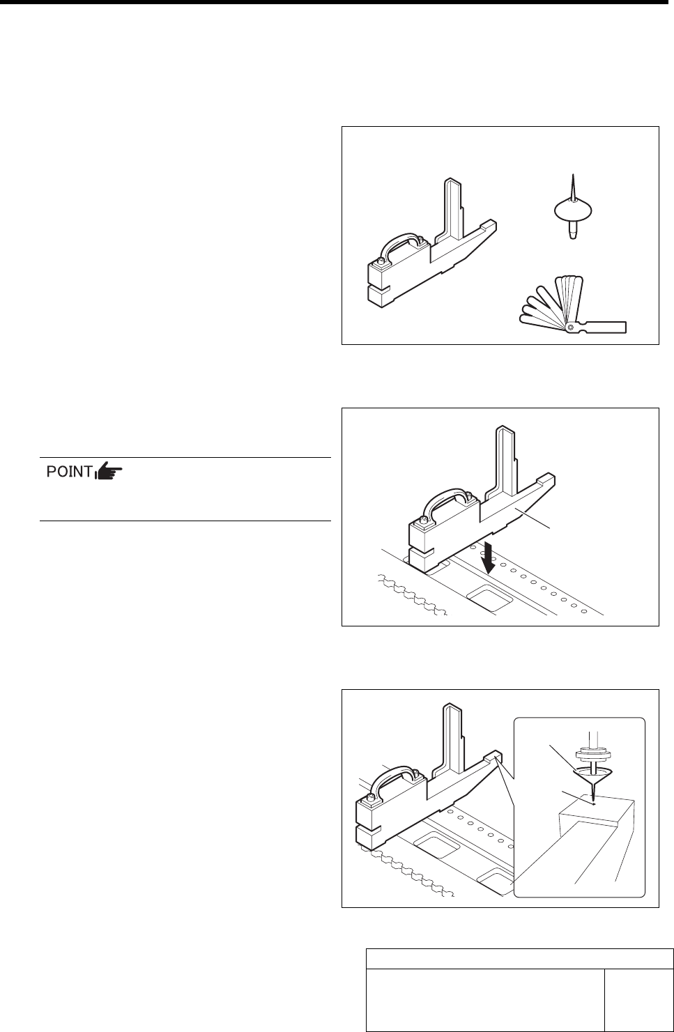
[Necessary jigs]
• Feed adjusting jig
• Nozzle jig (AF06040)
• Thickness gauge (t=1.0 mm)
[Procedure]
1 Set the feed adjusting jig to the No.20 posi-
tion on the cassette table.
There should be no clearance between the
feed adjusting jig and the cassette table.
2 Install nozzle jig (AF06040) to the turret.
3 Move the head to a position where the noz-
zle jig can be inserted into the insertion hole
of the feed adjusting jig.
Feed adjusting jig
Nozzle jig
(AF06040)
Thickness gauge
Feed adjusting jig
Nozzle jig
Insertion
hole
Adjustment of FF/FR Axis Feed Roller X-Direction Position
HLF-10412-01
Adjustment of FF/FR Axis Feed
Roller X-Direction Position
SHEET
2/2
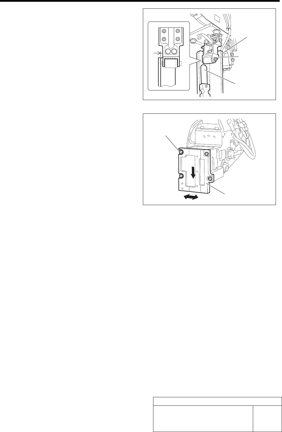
4 Lower the feed roller by hand to check
clearance in the X direction with the feed
adjusting jig.
1. Check that thickness gauge of t = 1
mm cannot be inserted into the gap in
X direction between the feed roller
bracket and the feed adjusting jig.
2. Visually check that the feed roller
bracket does not contact the feed ad-
justing jig.
5 If the clearance is out of the standard, shift
the feed roller attachment plate position to
adjust the clearance.
1. Loosen the cap screws (4-M4) on the
feed roller attachment plate.
2. Move the feed roller attachment plate
to left and right to adjust the clearance
while pushing it downward.
3. Fasten the cap screws (4-M4) at a po-
sition where the clearance is within
the standard and fix the feed roller
attachment plate.
6 After adjusting the position, recheck that the
nozzle jig can be inserted into the feed ad-
justing jig inserting hole.
Thickness gauge
Feed adjusting jig
Feed roller
bracket
Cap screw
Feed roller attachment plate