SI-F130 Manual(EN)_jpg_ Rev1.pdf - 第102页
H Axis Gear Z-phase Matching HLF-10403-01 H A xis Gear Z-phase Matchi ng SHEET 2/4 3 Remove the lower end senso r (H-CW) to- gether with the bracket. 4 Loosen split fastening screw on the H axis motor pinion to make free…
H Axis Gear Z-phase Matching
HLF-10403-01
H Axis Gear Z-phase Matching
SHEET
1/4
H Axis Gear Z-phase Matching
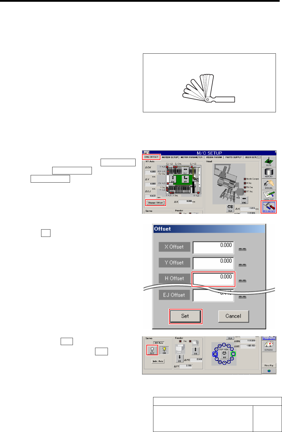
[Necessary jigs]
• Thickness gauge (t=1.0 mm)
[Procedure]
1 Set the H Axis offset to "0".
1. Click in an order of the M/C SETUP
menuÎORG OFFSET tabÎ
Change Offset button.
Offset screen is displayed.
2. Input "0" in the H Offset box, and click
the Set button.
H offset value is set, and the Offset screen closes.
2 Click the servo OFF button for all axes.
1. Click the all axes servo OFF button on
the ORG. OFFSET screen.
Servos for all axes are turned off.
Thickness gauge (t=1.0mm)
H Axis Gear Z-phase Matching
HLF-10403-01
H Axis Gear Z-phase Matching
SHEET
2/4
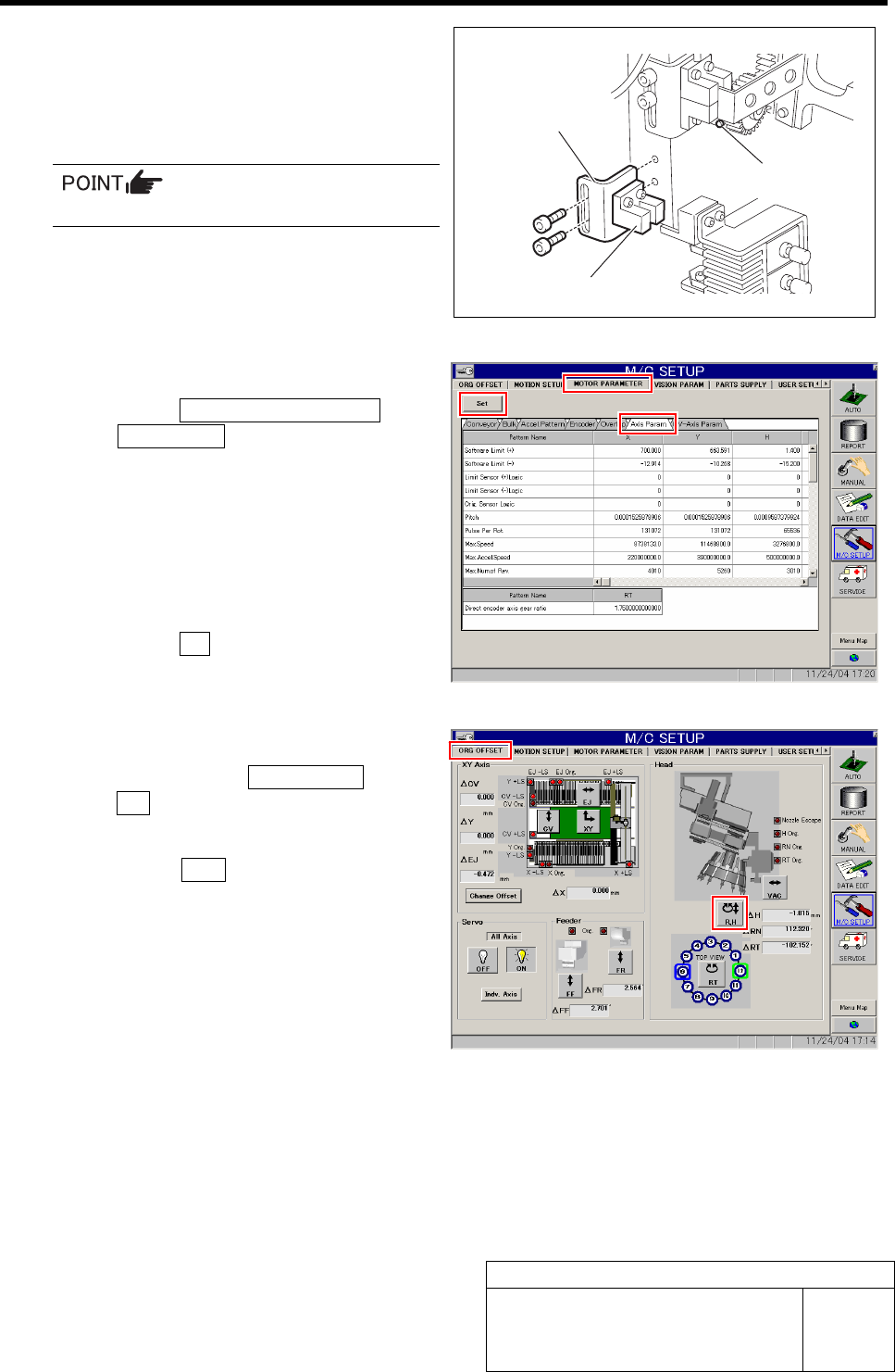
3 Remove the lower end sensor (H-CW) to-
gether with the bracket.
4 Loosen split fastening screw on the H axis
motor pinion to make free from motor shaft.
Rotate pinion for easy access of alain key.
5 Change the servo parameter for the H axis.
1. Click the MOTOR PARAMETER tab
ÎAxis Param. tab.
2. Change the next servo parameter for
the H axis.
Speed loop gain : 260.0 Î 50
Speed loop integral time
constant : 3.07 Î 12.73
Position loop gain : 371.4 Î 78.54
3. Click the Set button.
The changed parameters are set.
6 Perform origin position return for H axis only.
1. Click in an order of ORG OFFSET tab
ÎR.H button.
RN/H Axis screen is displayed.
2. Press the ORG button on the operation
panel with the RN/H Axis screen being
displayed.
Origin position return is performed for the H axis
only.
Bracket
Lower end sensor (H-CW)
Split fastening screw
H Axis Gear Z-phase Matching
HLF-10403-01
H Axis Gear Z-phase Matching
SHEET
3/4
7 Check that the motor shaft is idling while
origin position return is performed, once
escape the dog for H axis sensor from the
ORG sensor.
The motor shaft slowly stops in Z-phase after a few
seconds.
Unless the gear is free against the motor
shaft of the H axis, the dog obstructs the
CCW sensor and the servo is turned off.
Check that the gear is completely free
against the motor shaft of the H axis.
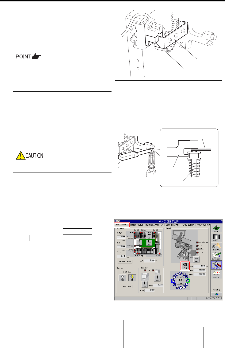
8 Check if the inner shaft lowers by pushing
upward.
9 Adjust the clearance between the H axis
pusher and inner shaft end to 1.0 mm, and
secure the H axis motor gear by split fas-
tening screw.
Be careful to prevent hand from being caught
because of work with servo ON.
1. Insert a thickness gauge of 1.0 mm
into the clearance between the H axis
pusher and inner shaft end.
2. Tighten the split fastening screw for
the H axis motor gear.
3. Remove the thickness gauge.
10 Perform origin position return for H axis only.
1. Click in an order of ORG OFFSET tab
ÎR.H button.
RN/H Axis screen is displayed.
2. Press the ORG button on the operation
panel with the RN/H Axis screen being
displayed.
Origin position return is performed for the H axis
only.
Dog
ORG sensor
Thickness gauge
H axis pusher
Inner shaft