SI-F130 Manual(EN)_jpg_ Rev1.pdf - 第103页
H Axis Gear Z-phase Matching HLF-10403-01 H A xis Gear Z-phase Matchi ng SHEET 3/4 7 Check that the motor shaf t is idling while origin position return i s performed, once escape the dog for H axis sensor from the ORG se…
H Axis Gear Z-phase Matching
HLF-10403-01
H Axis Gear Z-phase Matching
SHEET
2/4
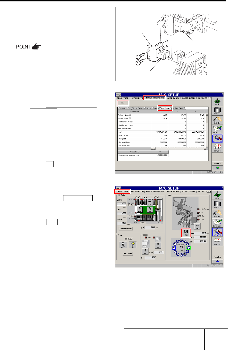
3 Remove the lower end sensor (H-CW) to-
gether with the bracket.
4 Loosen split fastening screw on the H axis
motor pinion to make free from motor shaft.
Rotate pinion for easy access of alain key.
5 Change the servo parameter for the H axis.
1. Click the MOTOR PARAMETER tab
ÎAxis Param. tab.
2. Change the next servo parameter for
the H axis.
Speed loop gain : 260.0 Î 50
Speed loop integral time
constant : 3.07 Î 12.73
Position loop gain : 371.4 Î 78.54
3. Click the Set button.
The changed parameters are set.
6 Perform origin position return for H axis only.
1. Click in an order of ORG OFFSET tab
ÎR.H button.
RN/H Axis screen is displayed.
2. Press the ORG button on the operation
panel with the RN/H Axis screen being
displayed.
Origin position return is performed for the H axis
only.
Bracket
Lower end sensor (H-CW)
Split fastening screw
H Axis Gear Z-phase Matching
HLF-10403-01
H Axis Gear Z-phase Matching
SHEET
3/4
7 Check that the motor shaft is idling while
origin position return is performed, once
escape the dog for H axis sensor from the
ORG sensor.
The motor shaft slowly stops in Z-phase after a few
seconds.
Unless the gear is free against the motor
shaft of the H axis, the dog obstructs the
CCW sensor and the servo is turned off.
Check that the gear is completely free
against the motor shaft of the H axis.
8 Check if the inner shaft lowers by pushing
upward.
9 Adjust the clearance between the H axis
pusher and inner shaft end to 1.0 mm, and
secure the H axis motor gear by split fas-
tening screw.
Be careful to prevent hand from being caught
because of work with servo ON.
1. Insert a thickness gauge of 1.0 mm
into the clearance between the H axis
pusher and inner shaft end.
2. Tighten the split fastening screw for
the H axis motor gear.
3. Remove the thickness gauge.
10 Perform origin position return for H axis only.
1. Click in an order of ORG OFFSET tab
ÎR.H button.
RN/H Axis screen is displayed.
2. Press the ORG button on the operation
panel with the RN/H Axis screen being
displayed.
Origin position return is performed for the H axis
only.
Dog
ORG sensor
Thickness gauge
H axis pusher
Inner shaft
H Axis Gear Z-phase Matching
HLF-10403-01
H Axis Gear Z-phase Matching
SHEET
4/4
11 Check that the clearance between the H axis pusher and inner shaft is 1.0 mm by thickness gauge.
Unless the clearance is 1.0 mm, it is necessary to re-perform “H axis origin position setup”.
12 Install the H axis lower end sensor (H-CW).
Perform position adjustment of the lower end sensor (H-CW) in the post-process of “Adjustment
H axis lower end OT sensor (H-CW)”.
13 Return the servo parameter of the H axis to the previous value.
Return the H axis parameter changed in the procedure 5 to the previous value and click the Set button.