SI-F130 Manual(EN)_jpg_ Rev1.pdf - 第100页
Matching of Y Axis Z-Phase HLF-10402-01 Matching of Y Axis Z-Phase SHEET 3/3 8 T urn the emergency stop switch in the arrow di rection to release the emergency stop st ate. 9 Press the ORG button on the operation p anel …
Matching of Y Axis Z-Phase
HLF-10402-01
Matching of Y Axis Z-Phase
SHEET
2/3
5 Measure the dog detection position of the
ORG sensor.
1. Measure the distance from the LM
guide rail end to the LM guide face
with a scale.
Suppose that the measured value is B.
(Example : 135.5 mm)
By 2 times of measurements, the amount of movements from the dog detection position of an
ORG sensor to the present Z-phase position can be found.
Suppose that the present amount of movement is C.
Example
: A (116 mm) - B (135.5 mm) = C (
-
19.5 mm)
6 The difference between the present mount of movement and the amount of Z-phase set-up
movement “5 mm” is searched for. Suppose that this difference is D.
Example : Present amount of movement (-19.5 mm) + Amount of Z-phase movement (5 mm) = D (-14.5 mm)
Since the present amount of movements is too as large as -19.5 mm against the set amount of movement “5 mm”, the ad-
justment made small 14.5 mm is required of this example.
7 Adjust the Z-phase set-up position.
Adjust the Z-phase set-up position by adjusting the positional relation between the motor and
ball screw.
1. Move the head to the center of Y axis
to secure working space to loosen the
coupling screws.
2. Loosen the screw M4 on the ball screw
side of the coupling.
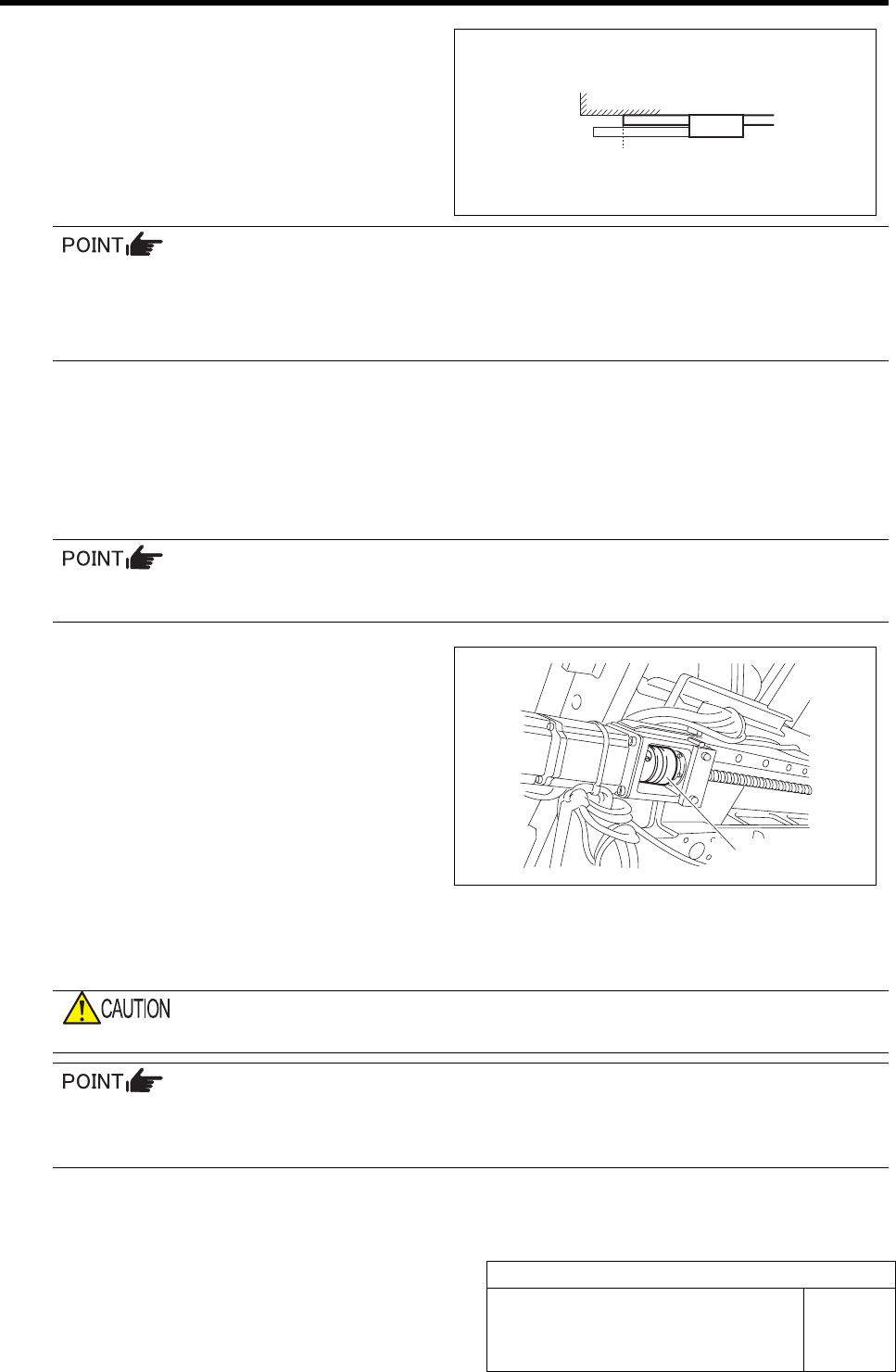
3. Measure the distance from the LM
guide rail end to the LM guide face
with a scale. (Example : 134 mm)
Suppose that this measured value is E.
E (134 mm) - D (-14.5 mm) = target dimension (148.5 mm)
4. Move the Y axis by dimension of the difference (D) with set-up movement found in the procedure 6.
Example : Adjust the Y axis so that the distance between the LM guide rail end and the LM guide face is 148.5 mm.
When the Y axis is moved, the coupling should not be moved.
If the difference between the present amount of movements and the amount of Z-phase set-up
movement is positive, move the Y axis to the CCW sensor side (front direction), and if the dif-
ference is negative, move it to the CW sensor (rear direction).
5. Fasten the screw M4 on the ball screw side of the coupling with a torque driver.
Tightening torque : 3.4N•m
B (135.5)
LM
Coupling

Matching of Y Axis Z-Phase
HLF-10402-01
Matching of Y Axis Z-Phase
SHEET
3/3
8 Turn the emergency stop switch in the arrow direction to release the emergency stop state.
9 Press the ORG button on the operation panel to perform origin position return.
10 Check the Z-phase set-up position.
1. Measure the distance from the LM guide rail end to the LM guide face with a scale.
Suppose that this measured value is A.
2. Measure the dog detection position of the ORG sensor with a scale.
Suppose that the measured value is B.
Check that a relation is obtained as A (Z-phase set-up position) = B - 5 mm (Z-phase set-up movement amount)
Tolerance level : ±1 mm
H Axis Gear Z-phase Matching
HLF-10403-01
H Axis Gear Z-phase Matching
SHEET
1/4
H Axis Gear Z-phase Matching
[Necessary jigs]
• Thickness gauge (t=1.0 mm)
[Procedure]
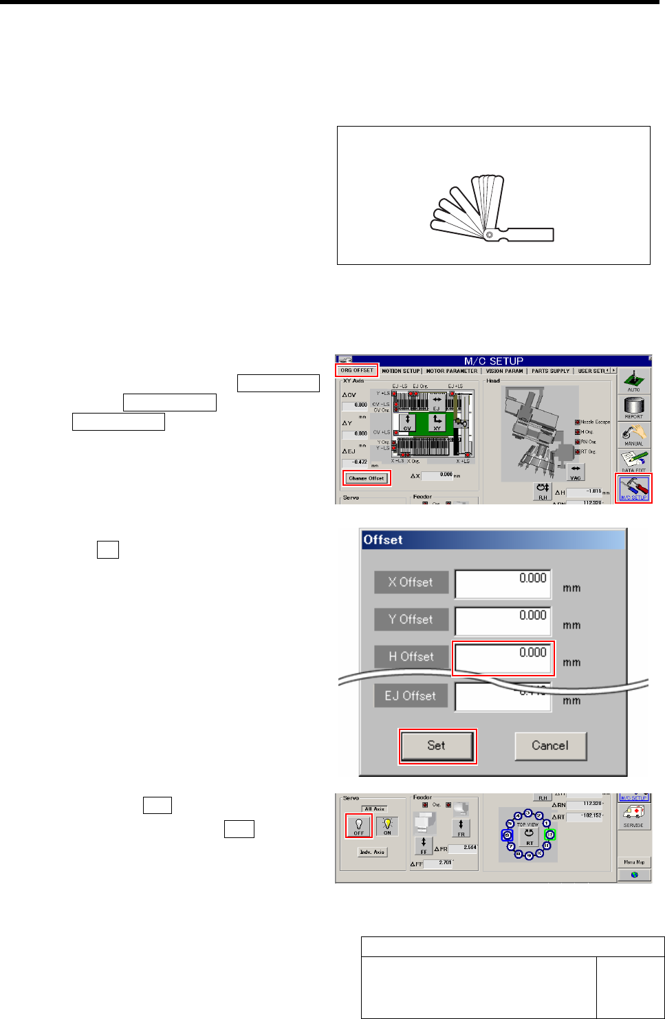
1 Set the H Axis offset to "0".
1. Click in an order of the M/C SETUP
menuÎORG OFFSET tabÎ
Change Offset button.
Offset screen is displayed.
2. Input "0" in the H Offset box, and click
the Set button.
H offset value is set, and the Offset screen closes.
2 Click the servo OFF button for all axes.
1. Click the all axes servo OFF button on
the ORG. OFFSET screen.
Servos for all axes are turned off.
Thickness gauge (t=1.0mm)