SI-F130 Manual(EN)_jpg_ Rev1.pdf - 第31页
PWB Camera Setup HLF-10204-01 PWB Camera Setup SHEET 4/4 10 Check again that the nozzle jig (AF06040) tip enters the nozzle inserting hole of the calibration plate jig by jog move. 1. Press the R.H button on the PWB came…
PWB Camera Setup
HLF-10204-01
PWB Camera Setup
SHEET
3/4
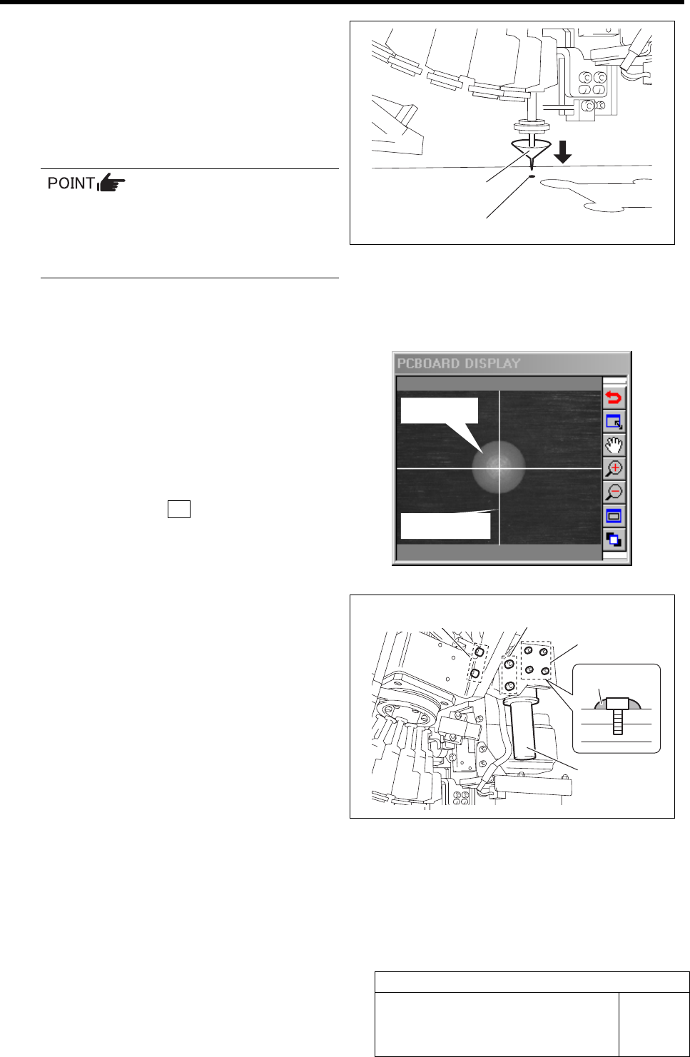
6 Adjust the head position so that the nozzle
jig (AF06040) tip enters the nozzle inserting
hole of the calibration plate jig.
1. Check whether the nozzle jig
(AF06040)
enters the nozzle inserting hole by
holding the inner shaft of the turret
No.1 by hand.
If the inner shaft is excessively lowered,
the H axis lower end limit works and the
units stops, then it is necessary to
re-perform from origin position return
(procedure 1).
2. When the position deviates, move the
XY axis by hand to finely adjust the
position.
7 When nozzle inserting position is deter-
mined, check the positions of white ball and
cross hairs on the PCBOARD DISPLAY.
8 Press the servo ON button on the PWB
Camera Setup screen.
Servos for X, Y and H axes are turned on.
9 Correct deviations of the white ball and
cross hairs by position adjustment of the
PWB camera.
1. Loosen the X, Y direction adjustment
screws of the PWB camera to adjust
the position of the PWB camera so that
the white ball mates center of the cross
hairs on PCBOARD DISPLAY.
When the white ball mates center of
the cross hairs, tighten the X, Y direc-
tion adjustment screws to secure the
PWB camera.
2. Loosen the focus adjustment screw to adjust the position of PWB camera so that the white
ball on PCBOARD DISPLAY the focuses.
When it focuses, tighten the focus adjustment screw to secure the PWB camera.
3. In order to prevent looseness, apply "adhesive agent:1401B" made by Three Bond on the
forcus adjustment screw.
Nozzle jig (AF06040)
Nozzle inserting hole
White ball
Cross hairs
Focus adjust-
ment screw
X direction
adjustment screw
Y
direction
adjustment screw
PWB camera
1401B
PWB Camera Setup
HLF-10204-01
PWB Camera Setup
SHEET
4/4
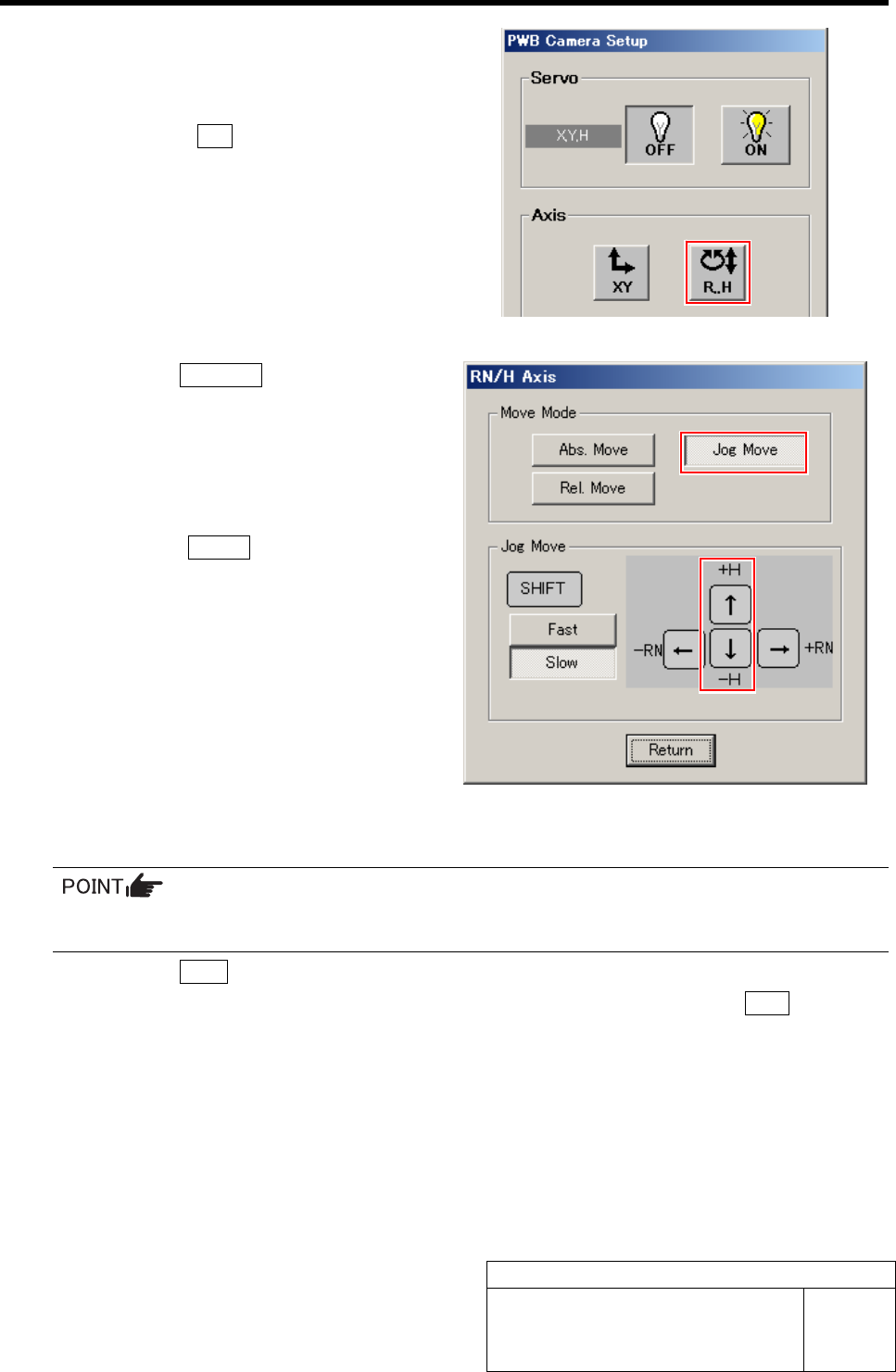
10 Check again that the nozzle jig (AF06040)
tip enters the nozzle inserting hole of the
calibration plate jig by jog move.
1. Press the R.H button on the PWB
camera Setup screen.
RN/H Axis screen is displayed.
2. Click the Jog Move button.
3. Jog move by the downward cursor key
to check that the nozzle jig (AF06040)
tip enters the nozzle inserting hole.
4. Press the upward cursor key to raise
the H axis.
5. Click the Return button to return to
the PWB Camera Setup screen.
11 Return to the HI screen to perform origin position return.
Since the position of the PWB camera itself has been adjusted, it is unnecessary to save the
position information here.
1. Click the Close button on the PWB Camera Setup screen.
2. Close the Machine Setup screen and CALIBRATION screen and press the ORG button on
the operation panel.
Origin position return is performed.
12 Remove the nozzle jig (AF06040).
Fiducial Mark Setup
HLF-10205-01
Fiducial Mark Setup
SHEET
1/2
Fiducial Mark Setup
[Necessary jigs]
• Do not use jig.
[Procedure]
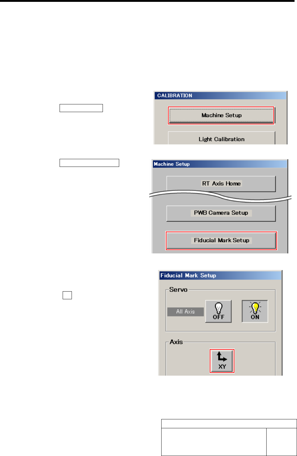
1 Display Fiducial Mark Setup screen.
1. Click the Machine Setup button on the
CALIBRATION screen.
Machine Setup screen is displayed.
2. Click the Fiducial Mark Setup button.
Fiducial Mark Setup screen is displayed.
2 Jog move the PWB camera to above the
target mark.
1. Click the XY button on the Fiducial
Mark Setup screen.
XY Axis screen is displayed.