SI-F130 Manual(EN)_jpg_ Rev1.pdf - 第12页
Install the Calibration Plate Jig HLF-10101-01 Install the Calibration Plate Jig SHEET 3/3 7 Perform the origin position return. 1. Press the RESET button on the operation panel to perf orm the initialization. 2. When “S…
Install the Calibration Plate Jig
HLF-10101-01
Install the Calibration Plate Jig
SHEET
2/3
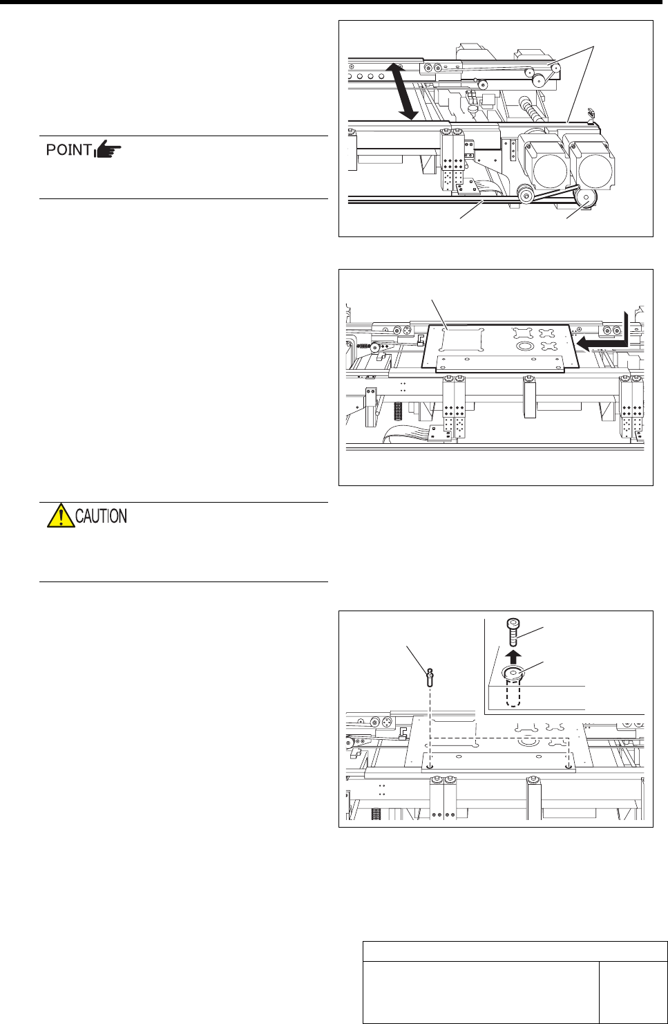
4 Manually move the pulley or belt for con-
veyor width adjusting motor to make the
width of the conveyor rail width to about the
width of calibration plate jig plus 0.5mm (ap-
proximately 120.5mm).
When in emergency stop status, the conveyor
width can be manually adjusted.
5 Install the calibration plate jig.
1. Place the calibration plate jig on the
rail on the right of the conveyor and
slide it to near the center of the con-
veyor.
2. Manually move the pulley or belt for
the conveyor width adjusting motor to
narrow the conveyor width.
3. Manually move the calibration plate
jig toward Y axis and check that
there’s slight rattle.
If installed with no gap between the calibra-
tion plate jig and rail, the calibration plate jig
may be deformed in clamping.
4. Insert the jig positioning pins (two)
into the calibration plate jig.
5. Remove the cap screw for jig position-
ing pin.
6 Turn the emergency stop switch in the arrow direction to release the emergency stop state.
Rail
Pulley Belt
Calibration plate jig
Jig positioning pin
Jig positioning pin
Cap screw
Install the Calibration Plate Jig
HLF-10101-01
Install the Calibration Plate Jig
SHEET
3/3
7 Perform the origin position return.
1. Press the RESET button on the operation panel to perform the initialization.
2. When “SYMC Initialize End” is displayed in the screen, press the FRONT button to turn
ON the servo.
3. Press the ORG button on the operation panel to start the origin position return.
When the origin position return is completed, the ORG button goes off.
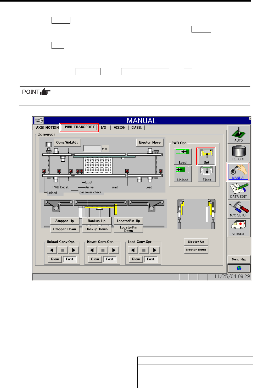
8 Fix the calibration plate jig.
1. Click in an order of MANUAL menuÎPWB TRANSPORT tabÎSet button.
Locator pin, Backup plate and Ejector simultaneously rise, and the calibration plate jig is fixed.
The risen portions are displayed in yellow on the screen.
Remove Production Nozzle
HLF-10102-01
Remove Production Nozzle
SHEET
1/2
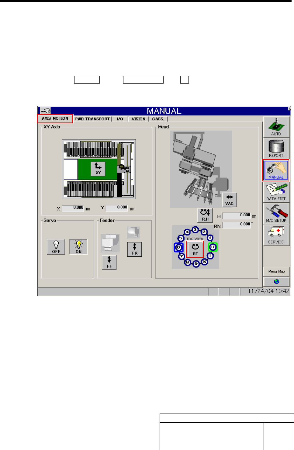
Remove Production Nozzle
Remove the nozzle used for production according to the procedure in this section because it is not
used for calibration operation.
[Procedure]
1 Click in an order of MANUAL menuÎAXIS MOTION tabÎRT button.
Turret RT Axis screen is displayed.