SI-F130 Manual(EN)_jpg_ Rev1.pdf - 第163页
Blow Flow rate S etup HLF-10425-01 Blow Fl ow r ate Se tup SHEET 2/4 3 Push the upper p art of the levers of the 12 mechanical valves on the head p art to be ready for blow-out. 4 Install the no zzle jigs (AF12080) to th…

Blow Flow rate Setup
HLF-10425-01
Blow Flow rate Setup
SHEET
1/4
Blow Flow rate Setup
This section describes a procedure to set up blow flow rate.
[Necessary jig]
• Flowmeter
• Flow rate measuring nozzle jig
• Nozzle jig (AF12080): 12 pieces
[Procedure]
1 Prepare flowmeter.
1. Turn on power for the flowmeter and warm up for one minute.
2. Check that the displayed value on the flowmeter is “0±0.009”.
When the displayed value on the flowmeter is not “0±0.009”, adjust the zero point in the fol-
lowing procedure.
1) Close the IN-OUT part on the flowmeter with tape to warm up for 30 minutes.
2) Carefully remove the serial number seal on the upper of the flowmeter main body until the
volume is seen.
3) Slowly turn the zero adjustment volume (remote from the signal connector) with precision
screw driver to adjust zero point.
4) After zero point adjustment, return the serial number seal to the previous state, and remove
the tape closing the IN-OUT part.
2 Turn off the VACUUM breaker.
1. Loosen 2 screws to remove the lower
panel on the front of the unit.
2. Turn off the VACUUM breaker on the
PC unit part.
VACUUM breaker
Flowmeter
Flow rate measuring
nozzle jig
Nozzle jig (AF12080)
Blow Flow rate Setup
HLF-10425-01
Blow Flow rate Setup
SHEET
2/4
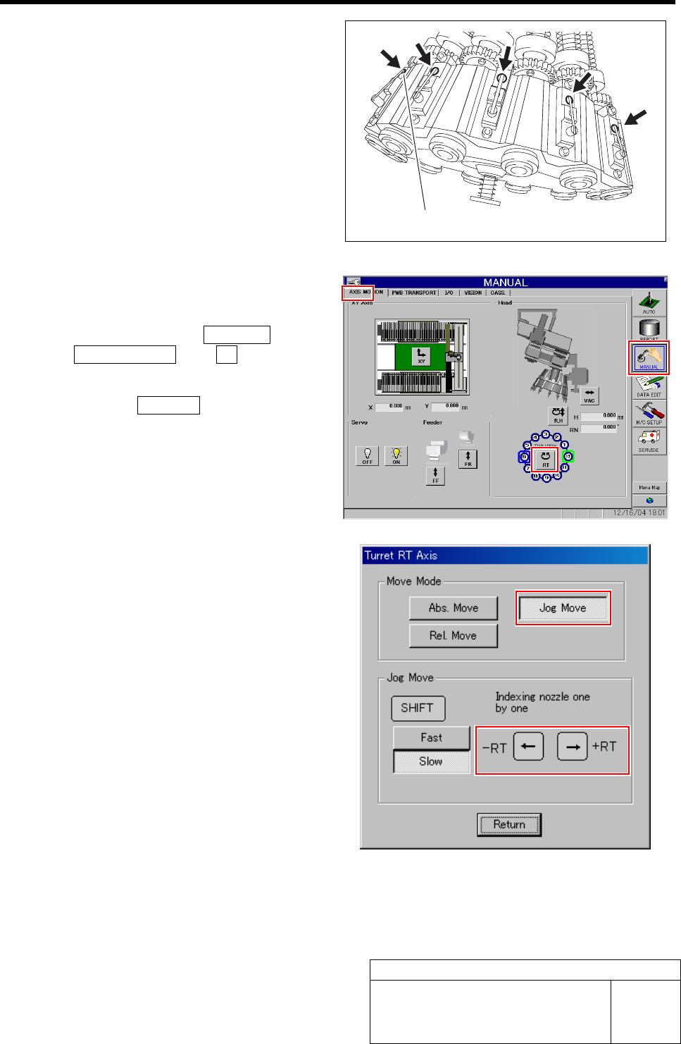
3 Push the upper part of the levers of the 12
mechanical valves on the head part to be
ready for blow-out.
4 Install the nozzle jigs (AF12080) to the tur-
rets No.2 to 12.
1. Click in an order of MANUAL menuÎ
AXIS MOTION tabÎXY button.
Turret RT Axis screen is displayed.
2. Click the Jog Move button in the move
mode.
3. Press the left and right cursor key to
rotate the turrets (No.2 to 12) to fit the
nozzle jig sequentially toward the
front, and install the nozzle jig.
Upper part of lever
Blow Flow rate Setup
HLF-10425-01
Blow Flow rate Setup
SHEET
3/4
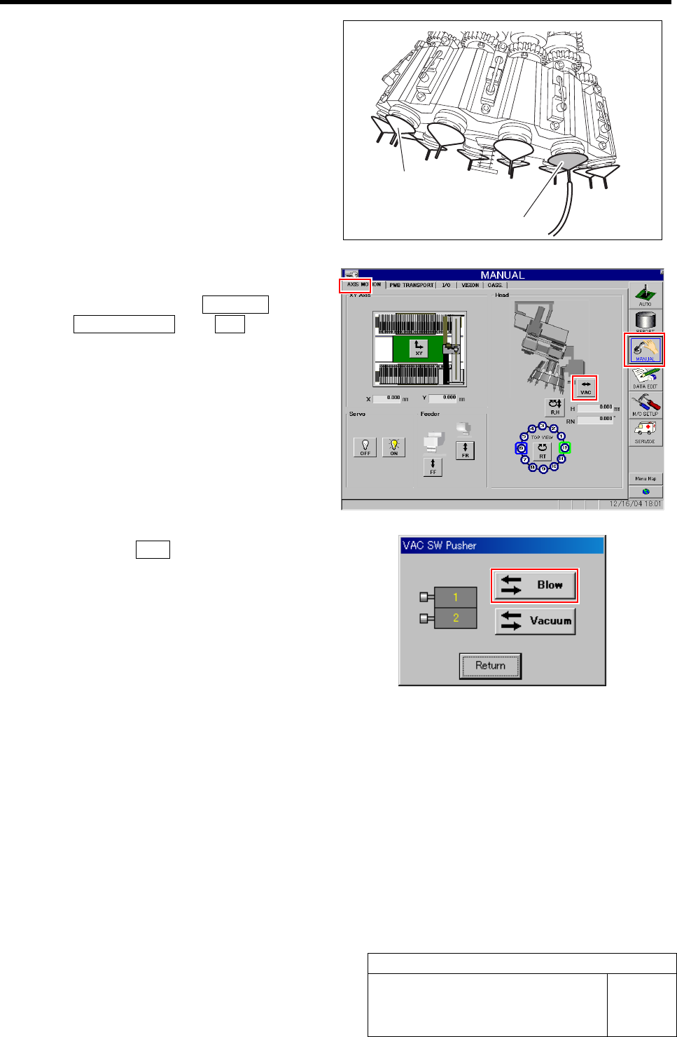
5 Install the flow rate measuring nozzle jig to
the turret No.1.
6 Turn on the blow.
1. Click in an order of MANUAL menuÎ
AXIS MOTION tabÎVA C button.
VAC SW Pusher screen is displayed.
2. Click the Blow button.
The blow is turned on.
3. Check that the value of the blow regu-
lator is “0.015 to 0.035 MPa” when in a
state of blow.
Flow rate measuring nozzle jig
Nozzle jig (AF12080)