SI-F130 Manual(EN)_jpg_ Rev1.pdf - 第146页
Phase Adjustment for Nozzle HLF-10418-01 Phase A djust ment for Nozzle SHEET 7/8 16 Install the phase adju sting jig for nozzle. 1. Check that screw for phase adjusting jig for nozzle is loosened. 2. While bringing up th…
Phase Adjustment for Nozzle
HLF-10418-01
Phase Adjustment for Nozzle
SHEET
6/8
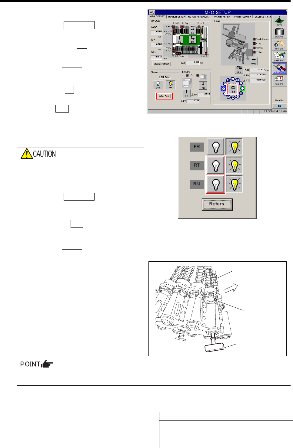
13 Perform origin position return of the RT axis.
1. Click the Indv. Axis button on the
ORG OFFSET screen to open the Indv.
Axis Servo screen.
2. Click the servo ON button for RT and
RN to turn on the servo.
3. Click the Return button to close the
Indiv. Axis servo screen.
4. Click the RT button on the ORG
OFFSET screen.
5. Press the ORG button on the operation panel
with the RT Axis screen being displayed.
Origin position return of the RT axis is performed.
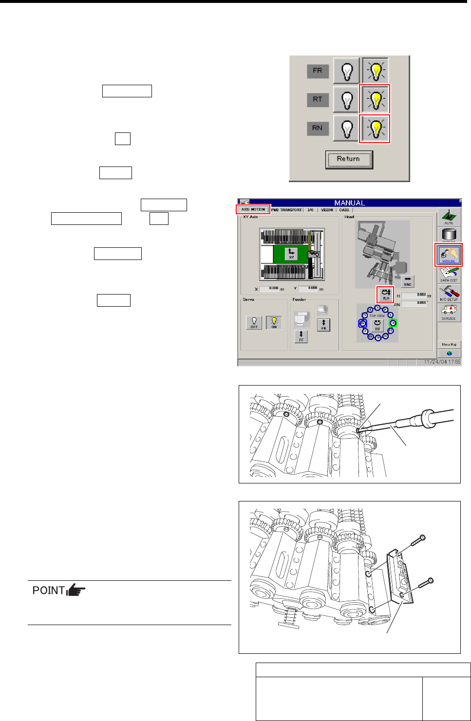
14 Again, turn off the RN, RT servos.
If working is carried out without turning off
the servo, hand or fingers may be caught in
the small gear. Be sure to turn OFF the
servo before working.
1. Click the Indv. Axis button on the
ORG OFFSET screen to display the
Indv. Axis Servo screen.
2. Click the servo OFF button for RT and RN.
Servo for RT, RN is turned off.
3. Click the Return button to close the
Indv. Axis servo screen.
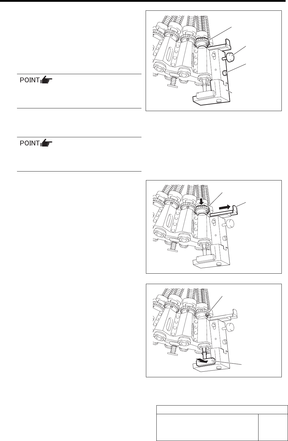
15 Install the phase adjusting jig and adjust the
direction of the inner shaft.
1. Install the phase adjusting jig to the
turret No.1.
2. Adjust the direction of the inner shaft
so that one line slot directs to outside
of the head.
The inner shaft has totally 3 slots of one line slot and 2 arranged slots.
When 2 slots are seen, turn the inner shaft by 180 degrees so that only one slot directs to outside.
3. Turn the small gear so that the left side screw for the small gear directs to outside of the
head.
Phase adjusting jig
Slot of inner shaft
Outside
Left side screw
Phase Adjustment for Nozzle
HLF-10418-01
Phase Adjustment for Nozzle
SHEET
7/8
16 Install the phase adjusting jig for nozzle.
1. Check that screw for phase adjusting
jig for nozzle is loosened.
2. While bringing up the small gear, in-
stall the phase adjusting jig for nozzle
onto the mechanical valve installing
surface by fastening the cap screws.
The phase adjusting jig for nozzle can be
installed with the phase adjusting jig be-
ing installed.
3. Check that the small gear is placed on
the lever, and fasten the screw for the
nozzle phase adjusting jig for nozzle.
When the screw for the phase adjusting jig
for nozzle is fastened, the lever is fixed with
being brought upward.
17 Pull out the lever, and fasten the left side
screw on the small gear.
1. Pull the lever to outside to check the
small gear shifts downward.
The small gear placed on the lever shifts down-
ward by pulling out the lever.
2. Push the phase adjusting jig against
the phase adjusting jig for nozzle by
hand, and fasten the left side screw
with a torque of 2kgf・m to fix while
checking that the left side screw for
the small gear directs to outside.
Phase adjusting jig
for nozzle
Cap screw
Screw
Small gear
Left side screw
Phase
adjustment jig
Lever
Small gear
Phase Adjustment for Nozzle
HLF-10418-01
Phase Adjustment for Nozzle
SHEET
8/8
18 Adjust nozzle phases of No.2 to 12 in the same way as in the procedures 15 to 17, and then remove
the phase adjusting jig for nozzle and phase adjusting jig.
19 Fasten all screws on the right side of the
small gear.
1. Click the Indv. Axis button on the
ORG OFFSET screen.
Indv. Axis servo screen is displayed.
2. Click the servo ON button for RT and RN.
Servo for RT, RN is turned off.
3. Click the Return button to close the
Indv. Axis servo screen.
4. Click in an order of MANUAL menuÎ
AXIS MOTION tabÎR.H button.
RN/H Axis screen is displayed.
5. Click the Abs. Move button.
6. Click the RN Axis button and input
“120” in angle input box.
7. Press the START button on the opera-
tion panel.
All of the inner shafts rotates by 120 degree and
right side screws of the small gear direct to out-
side.
8. Fasten all of the right side screws of
the small gear with a torque of
2kgf•m.
20 Install all mechanical valves.
1. Retighten the lower side cap screw
with a torque of 5kgf•m.
2. Retighten the upper side cap screw
with a torque of 5kgf•m.
When tightening the cap screw, retighten in
an order of upper side Î lower side screw.
21 Turn on the VACUUM breaker.
Torque driver
Right side screw
Mechanical valve