SI-F130 Manual(EN)_jpg_ Rev1.pdf - 第24页
H Axis Origin Position Setup HLF-10202-01 H A xis Origin Position Setup SHEET 2/2 3 Click the Setup S tart button. “Press [ST AR T ] to move to index 1 ” is displayed on the message screen. 4 Press the ST ART button on t…
H Axis Origin Position Setup
HLF-10202-01
H Axis Origin Position Setup
SHEET
1/2
H Axis Origin Position Setup
[Necessary jigs]
• Do not use jig.
[Procedure]
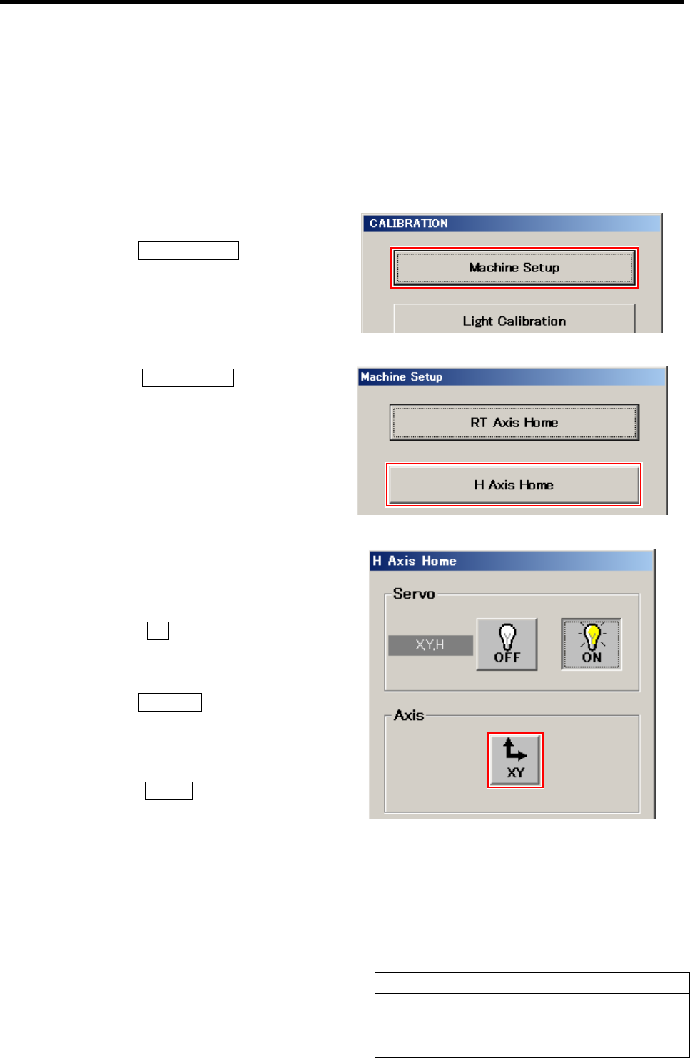
1 Display H Axis Home screen.
1. Click the Machine Setup button on the
CALIBRATION screen.
Machine Setup screen is displayed.
2. Click the H Axis Home button on the
Machine Setup screen.
H Axis Home screen is displayed.
2 Move the head unit to a position where
working is easily performed (center toward
you).
1. Click the XY button on the H Axis
Home screen.
XY Axis screen is displayed.
2. Click the Jog Move button.
3. Press the cursor key to jog move the
head unit to a position of center to-
ward you.
4. Click the Return button to return to
the H Axis Home screen.
H Axis Origin Position Setup
HLF-10202-01
H Axis Origin Position Setup
SHEET
2/2
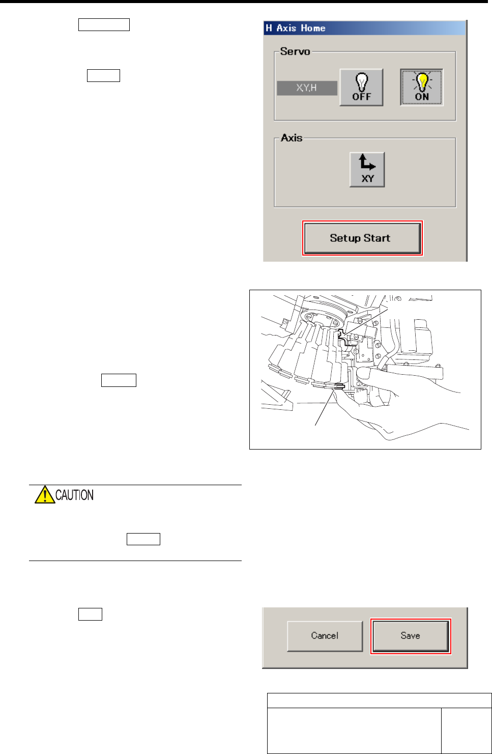
3 Click the Setup Start button.
“Press [START] to move to index 1” is displayed on
the message screen.
4 Press the START button on the operation
panel.
The inner shaft of the turret No.1 moves to directly
under the H axis pusher.
5 Set up H Axis Origin Position.
1. Support the inner shaft lower side by
hand.
2. Check that pushing lever is placed on
upper side of H axis.
3. Press the START button on the opera-
tion panel.
4. Release hand supporting the inner
shaft.
H axis origin position is automatically set up, RT axis
rotates and inner shaft for the next turret No. moves to
directly under the H axis pusher.
When the RT axis automatically rotates, fin-
ger or hand may be caught.
After pressing the START button, release
hand supporting the inner shaft lower side.
6 Repeat working of the procedure 5 up to No.12.
7 Click the Save button.
The H axis origin position is saved and H Axis Home
screen closes.
Lower inner shaft
Pushing lever
Acquiring Mounting Stroke Setup
HLF-10203-01
Acquiring Mounting Stroke Setup
SHEET
1/3
Acquiring Mounting Stroke Setup
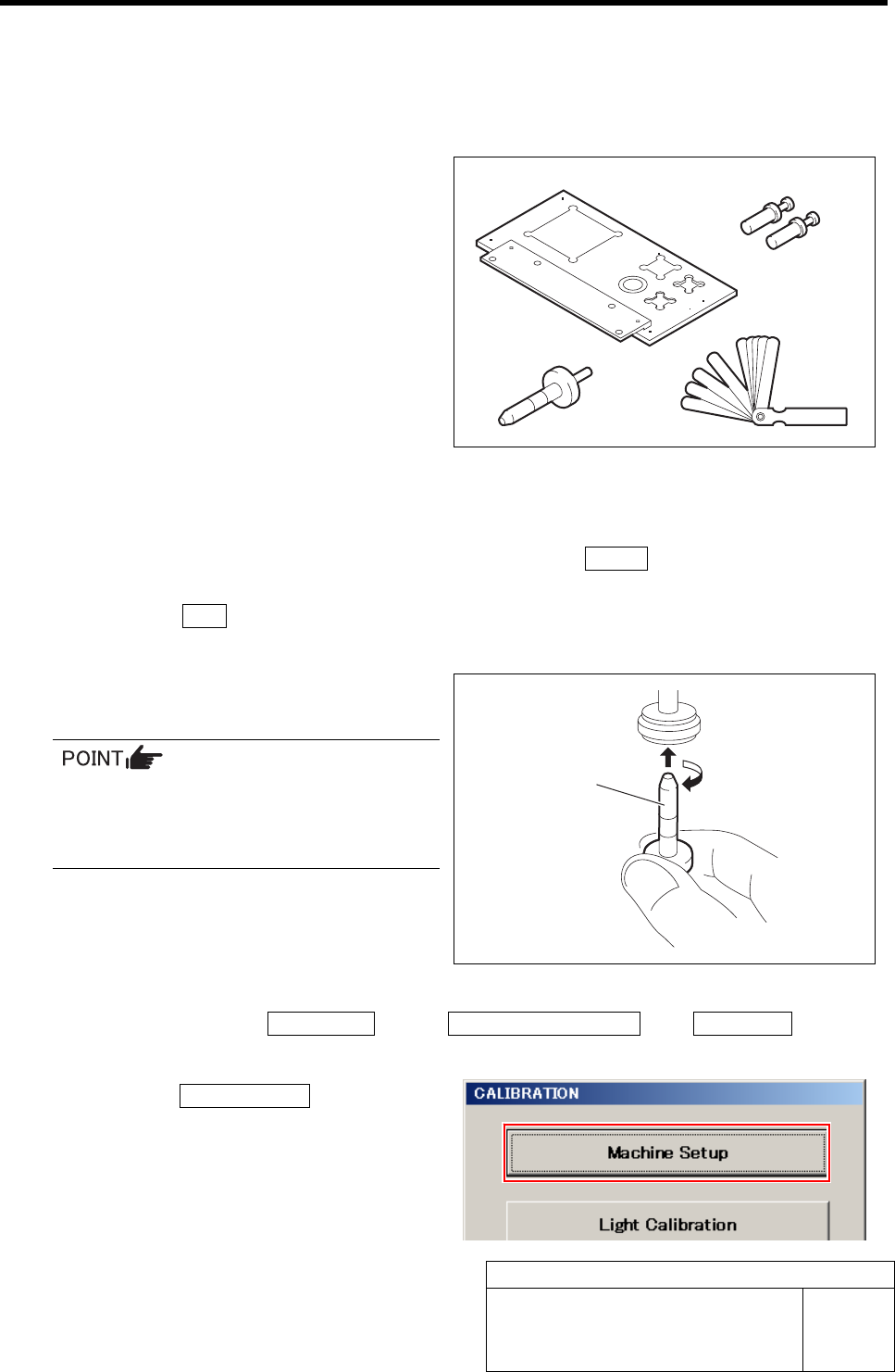
[Necessary jigs]
A Calibration plate jig
B Jig positioning pin
C Length reference nozzle jig
D Thickness gauge (t=0.03 mm)
[Procedure]
1 Perform the origin position return on the HI screen.
1. When the CALIBRATION screen is displayed, press the Return button to return to the HI
screen.
2. Press the ORG button on the operation panel.
Origin position return is performed.
2 Install the length reference nozzle jig to the
turret No.1.
When installing the nozzle, insert it while
slowly turning.
After inserting the nozzle, check that it is
not drawn out by pulling downward.
3 Display the Acquiring mounting stroke screen.
1. Click in an order of M/C SETUP menuÎM/C MAINTENANCE tabÎCalibration button.
CALIBRATION screen is displayed.
2. Click the Machine Setup button on the
CALIBRATION screen.
A
B
C D
Length reference
nozzle
j
i
g