SI-F130 Manual(EN)_jpg_ Rev1.pdf - 第159页
Ejector Setup HLF-10423-01 Ejector Setup SHEET 3/3 7 Release the emergency stop switch. 1. Return the pusher t o inside (right side) from t he OT sensor (CCW) respon ding position by hand. 2. T urn the emergency stop swi…
Ejector Setup
HLF-10423-01
Ejector Setup
SHEET
2/3
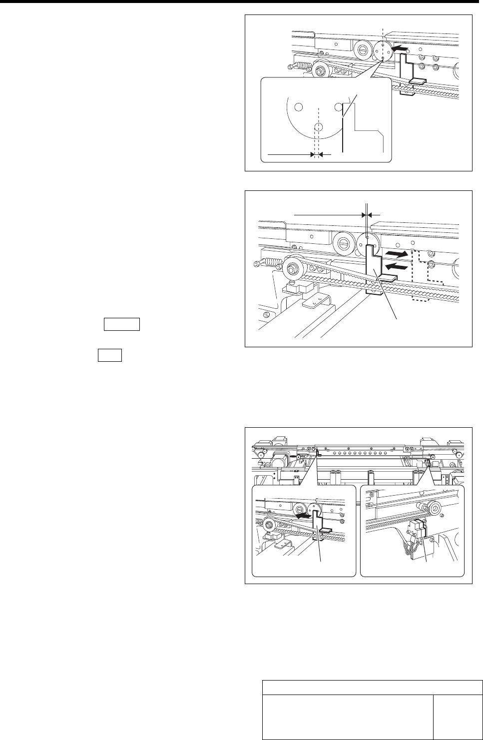
4 Adjust the pusher to the ORG position.
1. Loosen the pusher mounting bolts.
2. Move the pusher by hand so that the
pusher left face is at the ORG position.
3. Fasten the pusher mounting bolts to
fix the pusher.
5 After adjustment, check the ORG position.
1. Press the emergency stop switch to
turn off the servo.
2. Shift the pusher in right direction by
hand.
3. Turn the emergency stop switch in the
arrow direction to release the emer-
gency stop state.
4. Press the RESET button on the op-
eration panel.
5. Press the ORG button on the operation
panel with the Ejector Move screen
being displayed.
Check that the pusher returns to the position ad-
justed in the procedure 4.
6 Check the positions of the OT sensor (CCW)
and the mechanical stopper.
1. Press the emergency stop switch to
turn off the servo.
2. Move the pusher in left direction by
hand and check that the LED for the
OT sensor (CCW) lights up.
3. Further move the pusher in left direc-
tion and check that the pusher con-
tacts the mechanical stopper.
If the pusher contacts the mechanical stopper
prior to the OT sensor, adjust the sensor position
again.
Pusher left face
ORG
position
Pusher
ORG position
Pusher
OT sensor (CCW)
Ejector Setup
HLF-10423-01
Ejector Setup
SHEET
3/3
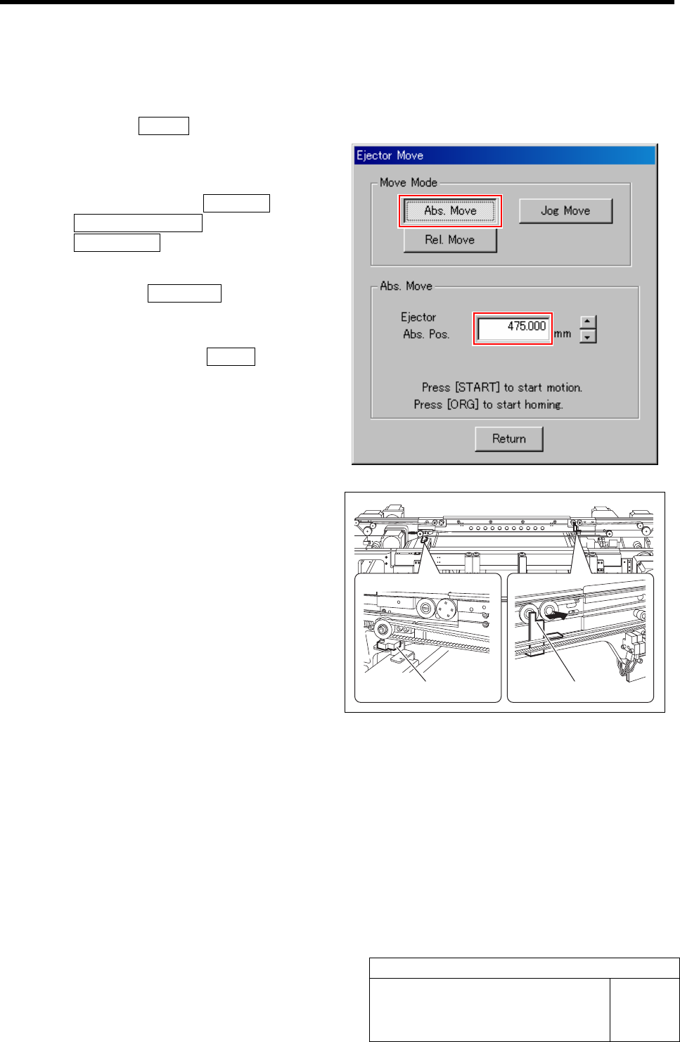
7 Release the emergency stop switch.
1. Return the pusher to inside (right side) from the OT sensor (CCW) responding position by
hand.
2. Turn the emergency stop switch in the arrow direction to release the emergency stop state.
3. Press the RESET button on the operation panel.
8 Check the positions of the OT sensor (CW)
and the mechanical stopper.
1. Click in an order of MANUAL menuÎ
PWB TRANSPORT tabÎ
Ejector Move button.
Ejector Move screen is displayed.
2. Click the Abs. Move button in the
Move Mode.
3. Input “475” in the Ejector Abs. Pos.
box, and press the START button on
the operation panel.
The ejector moves in right direction (to the posi-
tion of 475 mm).
4. Press the emergency stop switch to
turn off the servo.
5. Move the pusher in left direction by
hand and check that the LED for the
OT sensor (CW) lights up.
6. Further move the pusher in left direc-
tion and check that the pusher con-
tacts the mechanical stopper.
If the pusher contacts the mechanical stopper
prior to the OT sensor, adjust the sensor position
again.
OT sensor (CW)
Pusher
Adjustment of Bulk Unit Position
HLF-10424-01
Adjustment of Bulk Unit Position
SHEET
1/2
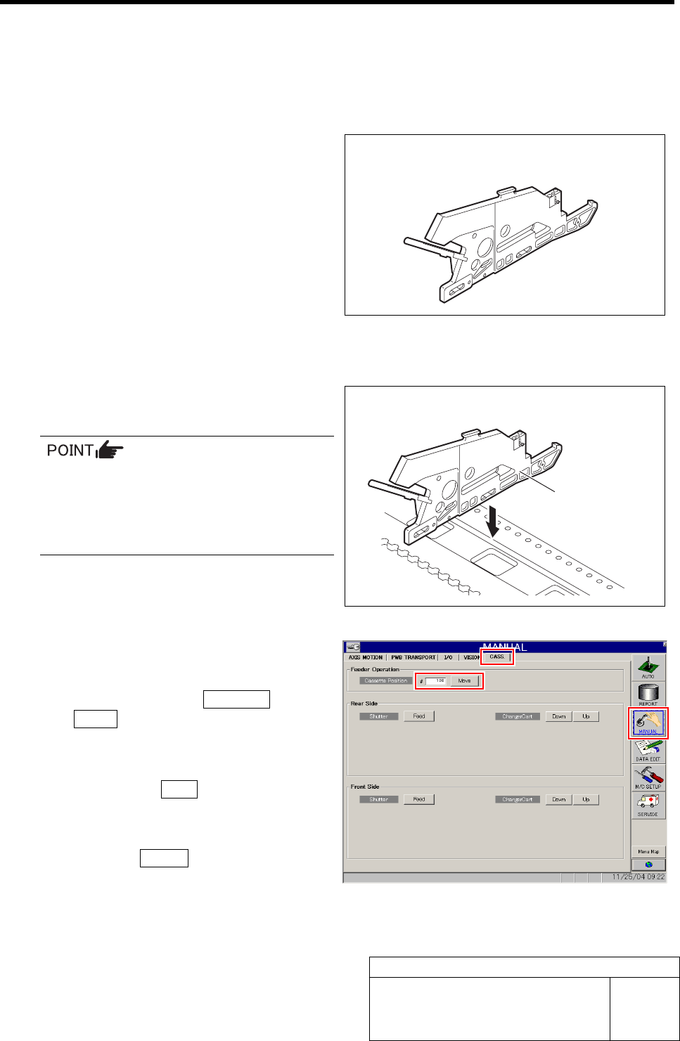
Adjustment of Bulk Unit Position
[Necessary jigs]
• Bulk cassette jig
[Procedure]
1 Set the bulk cassette jig at the position of
No.20 on the cassette table.
• There shall be no gap between the bulk
cassette jig and the cassette table.
• Set at the same jig position (front side
No.20) as set in the “Adjustment FF/FR
Axis Feed Roller X-Direction Position”.
2 Move the XY Axis to the position of cassette
No.20.
1. Click in an order of MANUAL menuÎ
CASS. tab.
Cassette operation screen is displayed.
2. Input “120” into the Cassette Position,
and click the Move button.
“Press [START] button to start Move” is dis-
played on the message screen.
3. Press the START button on the opera-
tion panel.
XY Axis moves to the position of cassette No.20.
Bulk cassette jig
Bulk cassette jig