SI-F130 Manual(EN)_jpg_ Rev1.pdf - 第149页
Adjustment of Cassette Float Sensor Height HLF-10420-01 Adjustment of Cassette Float Sensor Height SHEET 1/2 Adjustment of Cassette Float Sensor Height This section describes a procedure to adjust the height of the casse…
Adjustment of PWB Sensor
HLF-10419-01
Adjustment of PWB Sensor
SHEET
1/1
Adjustment of PWB Sensor
This section describes a procedure to adjust sensitivity and installing position of PWB detecting sensor (BS54,
BS50).
[Necessary jigs]
• Do not use jig.
[Procedure]
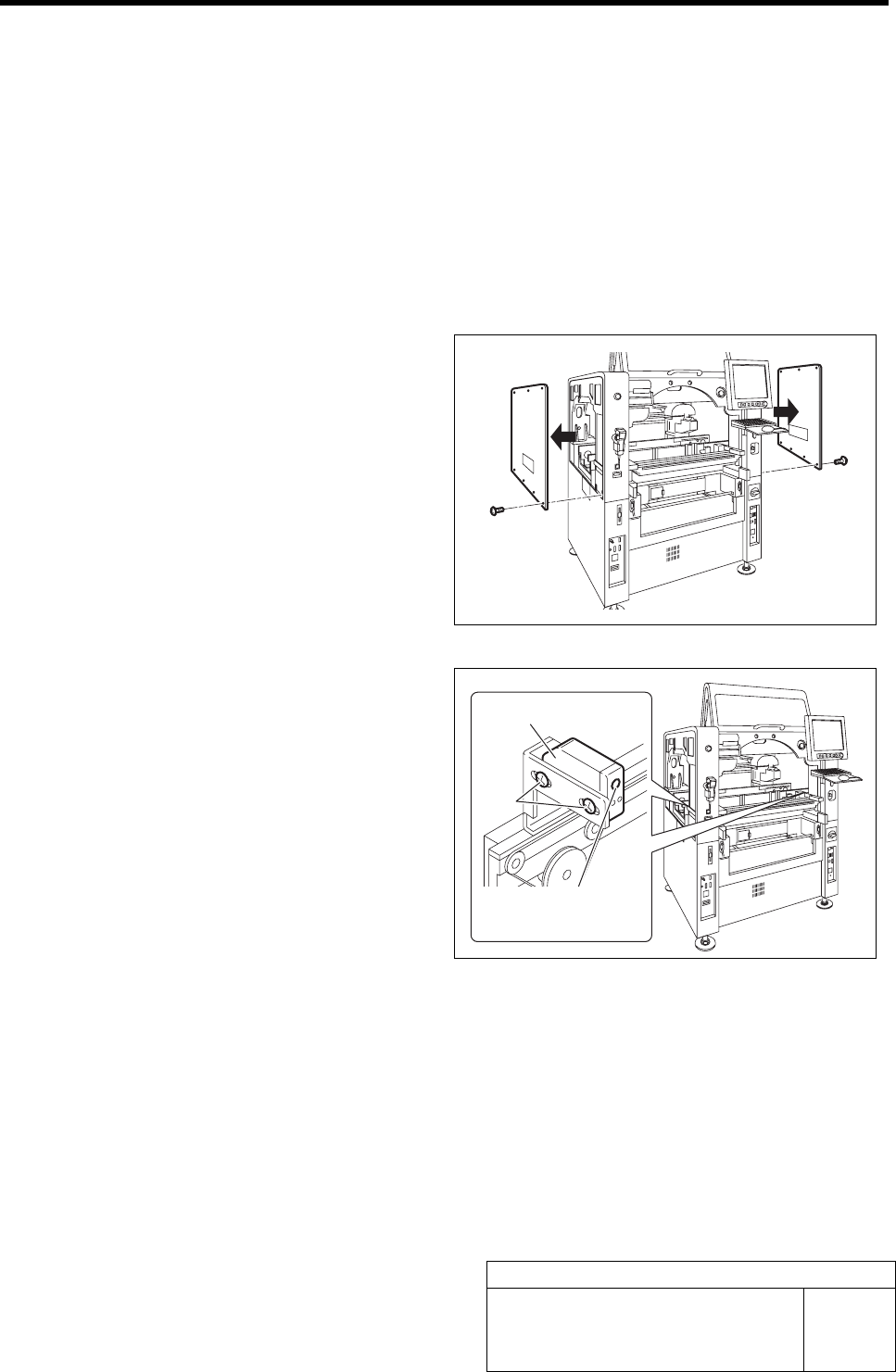
1 Remove the upper side panels on both sides
of the unit.
2 Adjust the sensitivity adjustment volume of
the PWB sensors (left side: BS54, right side:
BS50) installed on both ends of the con-
veyer to a position of 2/3.
3 Loosen the screw fastening the sensor, and
adjust the sensor position so that the screw
is at the center of the rectangular hole, and
then fasten the screw.
PWB sensor
Screw
Sensitivity
adjustment volume
Adjustment of Cassette Float Sensor Height
HLF-10420-01
Adjustment of Cassette Float Sensor
Height
SHEET
1/2
Adjustment of Cassette Float Sensor Height
This section describes a procedure to adjust the height of the cassette float sensor by using feed adjusting jig and
cassette float sensor height adjusting jig.
[Necessary jigs]
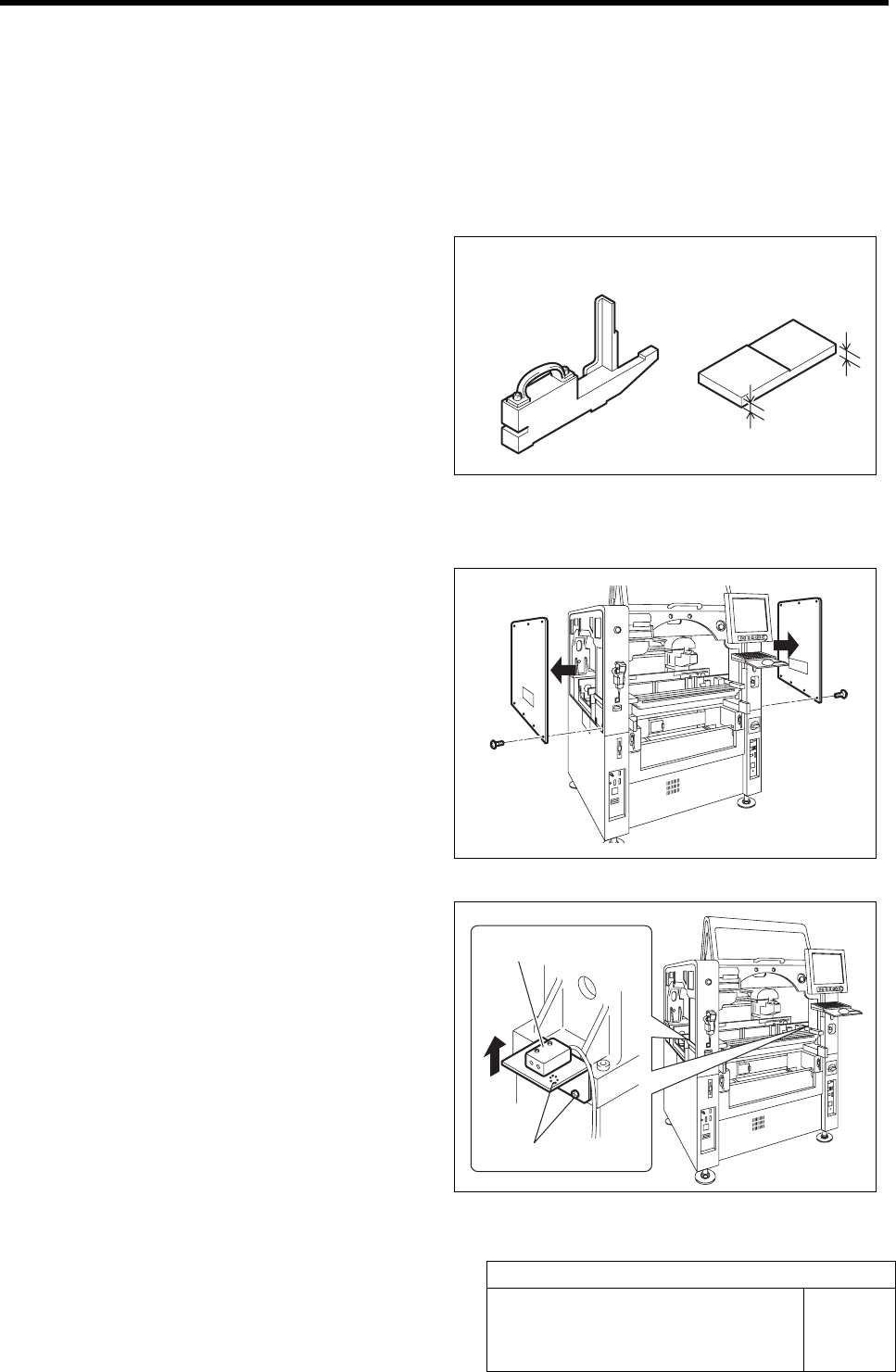
• Feed adjusting jig
• Cassette float sensor height adjusting jig
[Procedure]
1 Remove the upper side panels on both sides
of the unit.
2 Pull the bracket for the cassette float sensor
up to the upper end and temporarily tighten.
1. Loosen the cap screws (2-M4) on the
attachment bracket for the cassette
float sensors (left side: BS-63R, right
side: BS-63T) installed in the vertical
frame of the base stand.
2. Pull the bracket up to the upper end
and temporarily fasten.
3 Check that sensitivity level of BS-63R is
MAX.
Feed adjusting jig
Cassette float sensor
hei
g
ht ad
j
ustin
g
j
i
g
Cap screw
Cassette float sensor
6 mm
5 mm
Adjustment of Cassette Float Sensor Height
HLF-10420-01
Adjustment of Cassette Float Sensor
Height
SHEET
2/2
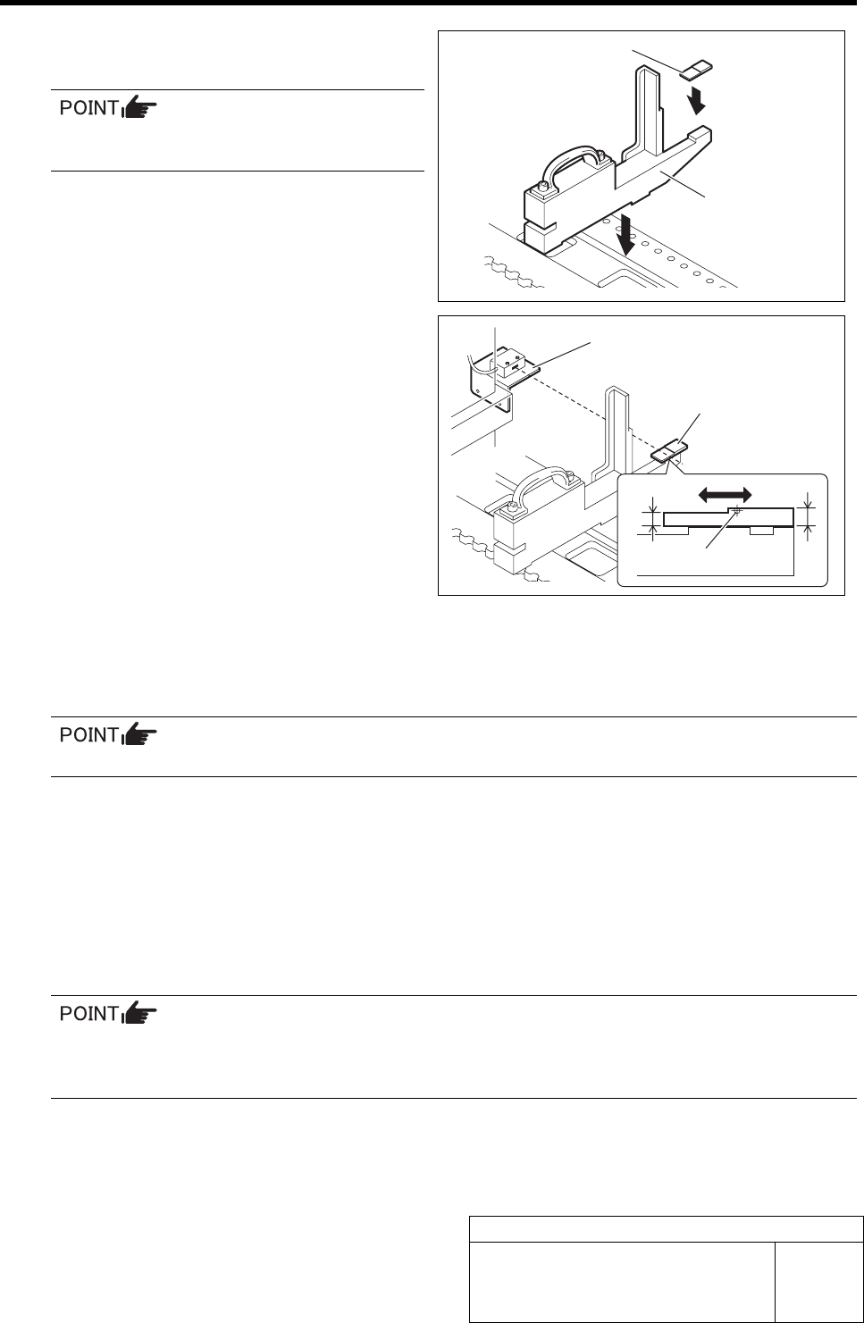
4 Set the feed adjusting jig to the No.1 position
on the cassette table.
There shall be no gap between the feed
adjusting jig and the cassette table.
5 Place the cassette float sensor height ad-
justing jig on the end of the feed adjusting
jig.
6 Adjust the height of the BS-63R.
1. Adjust the BS-63R attachment bracket
position so that the LED for the BS-63R
lights up at a part of 5 mm on the cas-
sette float sensor height adjusting jig,
and the LED extinguishes at a part of 6
mm.
2. Fasten the cap screw to fix the at-
tachment bracket.
3.
Again, move the cassette float sensor
height adjusting jig back and forth to
check that the LED turns ON/OFF well.
7 Adjust the height of the BS-63T attachment bracket at the position of No.39 on the cassette table.
1. Set the feed adjusting jig and cassette float sensor height adjusting jig on the position of
No.39 on the cassette table.
There should be no gap between the feed adjusting jig and the cassette table.
2. Adjust the height of the BS-63T attachment bracket in the same procedure as in the pro-
cedure 6.
8 Check that the LED for the BS-63R normally responds at the position of No.20 on the cassette table.
Check that the LED for the BS-63R lights up at a part of 5 mm on the cassette float sensor height adjusting jig, and the
LED extinguishes at a part of 6 mm.
9 Finally, again, check that the LEDs for the BS-63R and BS-63T normally respond at the positions of
No.1, 20 and 39 on the cassette table.
If the height is respectively adjusted at the positions of No.1, 20 and 39 on the cassette table,
response condition adjusted at the previous position varies. Be sure to check response of the
sensor at the 3 locations after adjustment.
10 Also, adjust the cassette float sensors (BS-64T, BS-64R) on the rear side in the same procedure as
the procedures 2 to 9.
Feed adjusting jig
Cassette float sensor
height adjusting jig
Cassette float sensor
height adjusting jig
Attachment bracket
5 mm
6 mm
Optical axis