SI-F130 Manual(EN)_jpg_ Rev1.pdf - 第94页
Conveyor Width Adjustment HLF-10316-01 Conv eyor Wid th Adju stmen t SHEET 2/2 3 Measure the conveyor widt h with digital slide calipers. 4 Display Offse t screen. 1. Click in an order of M/C SETUP menu Î ORG OFFSET tab …
Conveyor Width Adjustment
HLF-10316-01
Conveyor Width Adjustment
SHEET
1/2
Conveyor Width Adjustment
[Necessary jig]
• Do not use jig.
[Procedure]
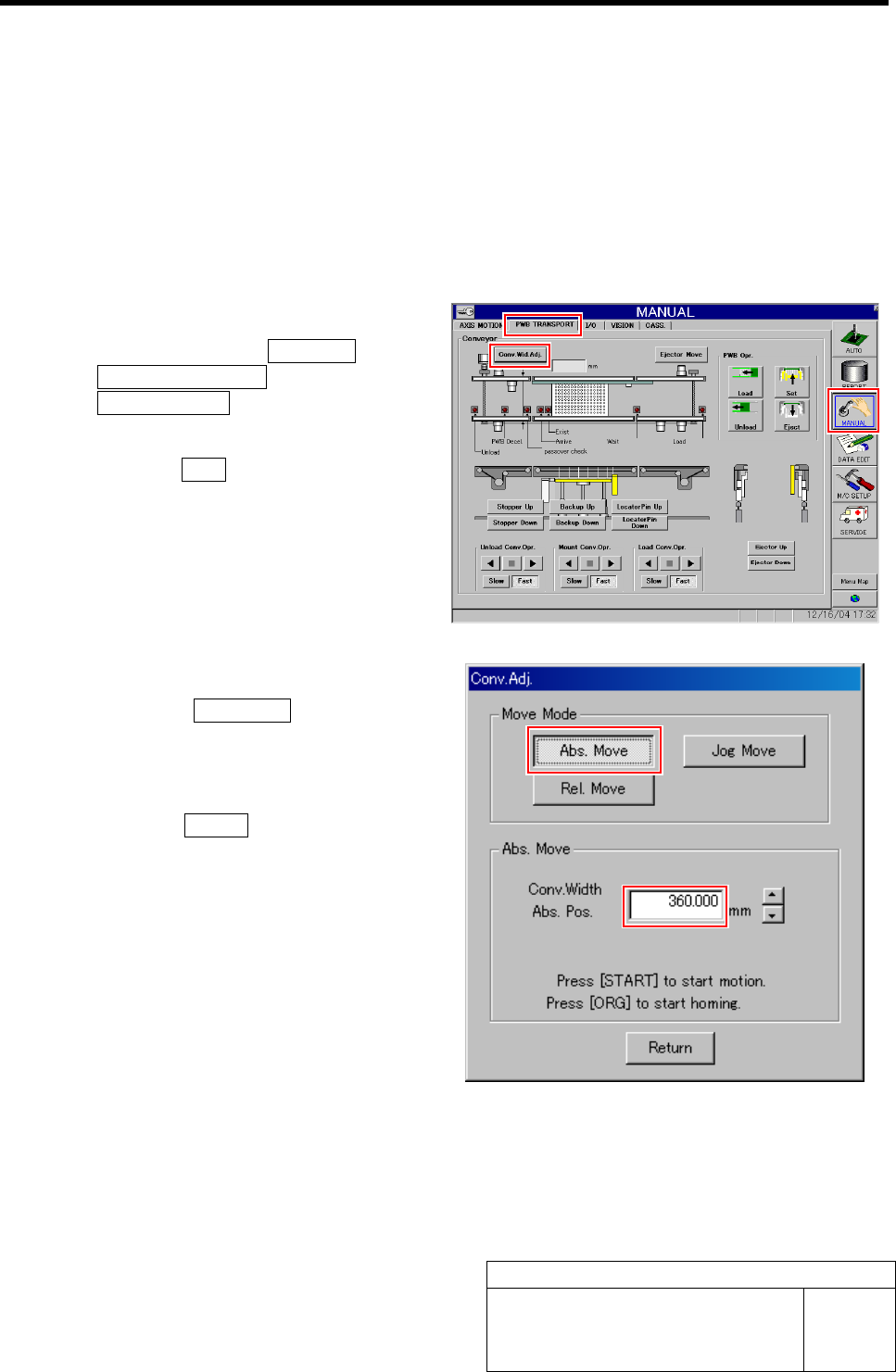
1 Perform origin position return of conveyor.
1. Click in an order of MANUAL menuÎ
PWB TRANSPORT tabÎ
Conv. Wid. Adj. button.
Conv. Adj. screen is displayed.
2. Press the ORG button on the operation
panel with the Conv. Adj. screen being
displayed.
Conveyor return to origin.
2 Set the conveyor width to 360 mm.
1. Click the Abs. Move button on the
Conv. Adj. screen.
2. Input “360” into the input box of the
Conv. Width Abs. Pos.
3. Press the START button on the opera-
tion panel.
Conveyor width is widened to the position of 360
mm.
Conveyor Width Adjustment
HLF-10316-01
Conveyor Width Adjustment
SHEET
2/2
3 Measure the conveyor width with digital slide
calipers.
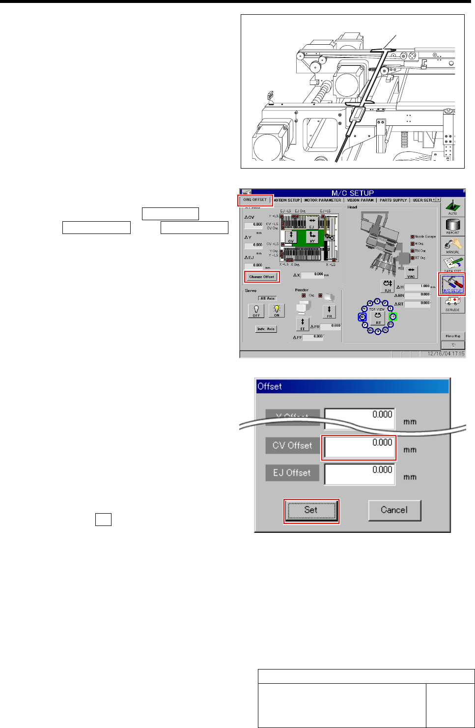
4 Display Offset screen.
1. Click in an order of M/C SETUP menu
ÎORG OFFSET tabÎChange Offset
button.
Offset screen is displayed.
2. Input the difference value between the
conveyor width measured in the pro-
cedure 3 and the standard value “360.5
mm” into the CV Offset box.
Example: Measured value: 360.0 mm
·········Input value “-0.5”
Measured value: 360.2 mm
·········Input value “-0.3”
3. Click the Set button.
The offset of the conveyor width is set and the
Offset screen closes.
5 Manually move the conveyor width to 360 mm again, and check that the conveyor width is within the
standard value (360.5 ±0.2 mm) with digital slide calipers in the same procedure as in the proce-
dures 1 to 3.
If the conveyor width is not within the standard value, repeat the procedures 1 to 4 until the conveyor width falls within
the standard value.
Digital slide calipers
Matching of X Axis Z-Phase
HLF-10401-01
Matching of X Axis Z-Phase
SHEET
1/3
Matching of X Axis Z-Phase
This section describes a procedure to adjust the Z-phase
position in such a way that the motor stops at the posi-
tion (Z-phase set-up position) where the ORG sensor
detects the dog and then moves by 5 ±1 mm toward the
X-CCW sensor side (left) when origin position return is
performed.
[Procedure]
1 Press the ORG button on the operation panel.
Origin position return is performed.
2 Measure the present Z-phase position.
1. Measure the distance from the frame
end face to the LM guide face on the
left side of the unit with a scale.
Suppose that the measured value is A.
(Example : 122.5 mm)
3 Press the emergency stop switch.
Servo is turned off.
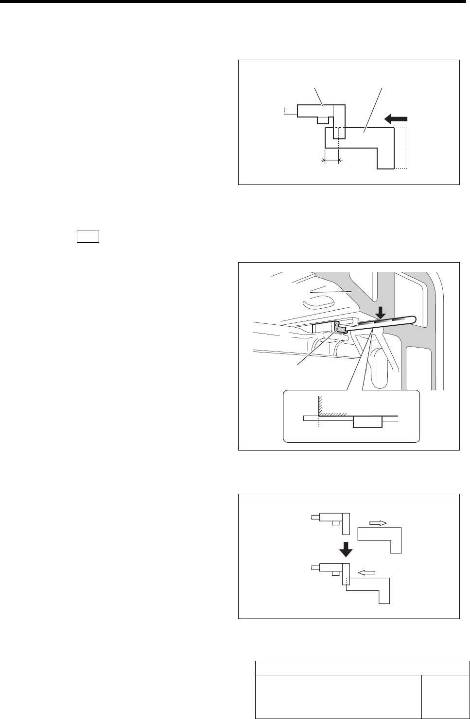
4 Stop the X axis at the boundary position
where the ORG sensor LED in extinguished
condition lights up.
1. Manually move the X axis in right di-
rection to the position where the dog
leaves the ORG sensor.
2. Manually move the X axis in left di-
rection little by little and stop at the
boundary position where the ORG
sensor LED in extinguished condition
lights up.
ORG sensor Dog
5 mm
A (122.5)
LM
Extinguished
Lights-up
Frame end face
LM guide face