SI-F130 Manual(EN)_jpg_ Rev1.pdf - 第78页
Fixed Camera Cali bration HLF-10313-01 Fixed Camera Calibration SHEET 7/7 17 After che cking the recogniti on result, click the Save button. The fixed camera c alibration result is saved, and the Fixed Camera Calibration…
Fixed Camera Calibration
HLF-10313-01
Fixed Camera Calibration
SHEET
6/7
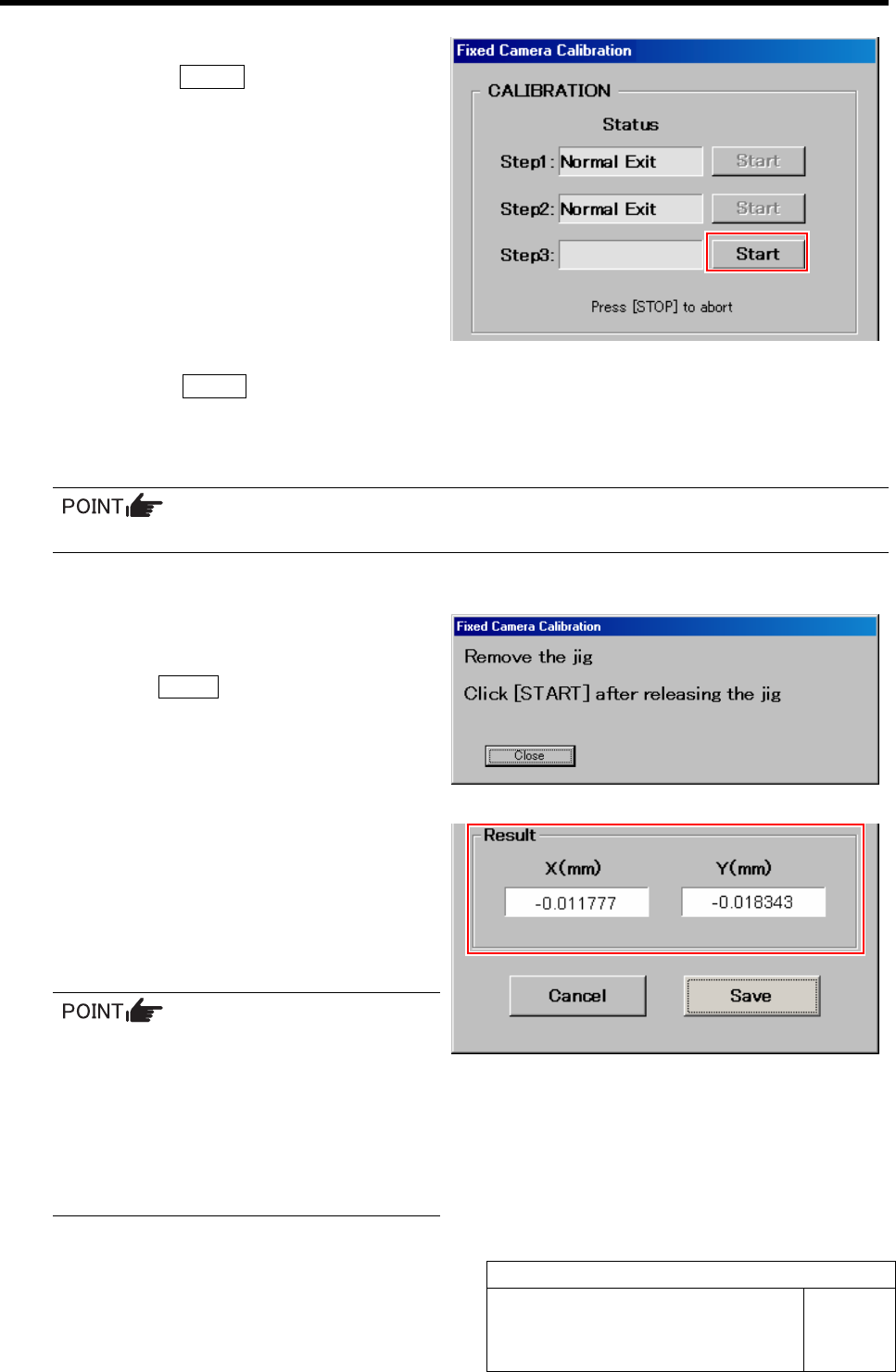
13 Start the Step 3.
1. Click the START button for Step 3.
“Press [START] to start Fixed camera calibra-
tion” is displayed on the message screen.
2. Press the START button on the operation panel.
Calibration check for the fixed camera is started, and after the PWB camera automatically recognizes 4 holes on the
right front of the fixed camera jig 2 in the same way as in the Step 2, it picks up the fixed camera jig 2 and recog-
nizes on the fixed camera.
If any error occurs, take same action as in the Step 2.
If normally ended, “Remove the jig. Click [START] after releasing the jig” is displayed on the message screen.
14 Remove the fixed camera jig 2 picked up by
the nozzle jig (AF80400).
15 Press the START button on the operation
panel.
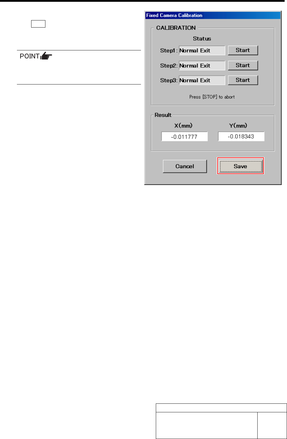
“Normal Exit” is displayed in the box for Step 3 on
the Fixed Camera Calibration screen and the recogni-
tion result is displayed.
16 Check the recognition result.
The recognition result is a guide for whether the cali-
bration is correctly performed or not. The closer
both of X and Y values to “0”, the higher the accuracy
is predicted to be.
• When the X, Y values are “0.1 and more”,
the value in a level in which placement
accuracy cannot be measured can not be
corrected, then re-perform fixed camera
calibration.
• When the X, Y values are “less than 0.1”,
the accuracy can be enhanced by cor-
recting the values.
Fixed Camera Calibration
HLF-10313-01
Fixed Camera Calibration
SHEET
7/7
17 After checking the recognition result, click
the Save button.
The fixed camera calibration result is saved, and the
Fixed Camera Calibration screen closes.
In order to store the calibration result in
the unit, be sure to re-start the unit before
operating the unit.
Pickup Position Setup
HLF-10314-01
Pickup Position Setup
SHEET
1/7
Pickup Position Setup
Pickup position setup can be performed at three locations on the front cassette table (Z106, Z120,
Z139) and at three locations on the rear cassette table (Z202, Z220, Z235).
Acquire XY position and H position by using jig at the respective position to setup pickup position.
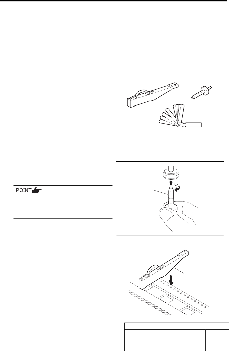
[Necessary jigs]
• Pickup point jig
• Length reference nozzle jig
• Thickness gauge (t=0.03 mm)
[Procedure]
1 Set the jig.
1. Install the length reference nozzle jig
to the turret No.1.
When installing the nozzle, insert it while
slowly turning.
After inserting the nozzle, check that it is
not drawn out by pulling downward.
2. Set pickup point jig to Z106 on the
cassette table.
Pickup point jig
Length reference
nozzle jig
Thickness gauge
Pickup point jig
Length reference
nozzle jig