SI-F130 Manual(EN)_jpg_ Rev1.pdf - 第96页
Matching of X Axis Z-Phase HLF-10401-01 Matching of X Axis Z-Phase SHEET 2/3 5 Measure the dog detection position of the ORG sensor . 1. Measure the distance fr om the frame end face to the LM guide face on the left side…
Matching of X Axis Z-Phase
HLF-10401-01
Matching of X Axis Z-Phase
SHEET
1/3
Matching of X Axis Z-Phase
This section describes a procedure to adjust the Z-phase
position in such a way that the motor stops at the posi-
tion (Z-phase set-up position) where the ORG sensor
detects the dog and then moves by 5 ±1 mm toward the
X-CCW sensor side (left) when origin position return is
performed.
[Procedure]
1 Press the ORG button on the operation panel.
Origin position return is performed.
2 Measure the present Z-phase position.
1. Measure the distance from the frame
end face to the LM guide face on the
left side of the unit with a scale.
Suppose that the measured value is A.
(Example : 122.5 mm)
3 Press the emergency stop switch.
Servo is turned off.
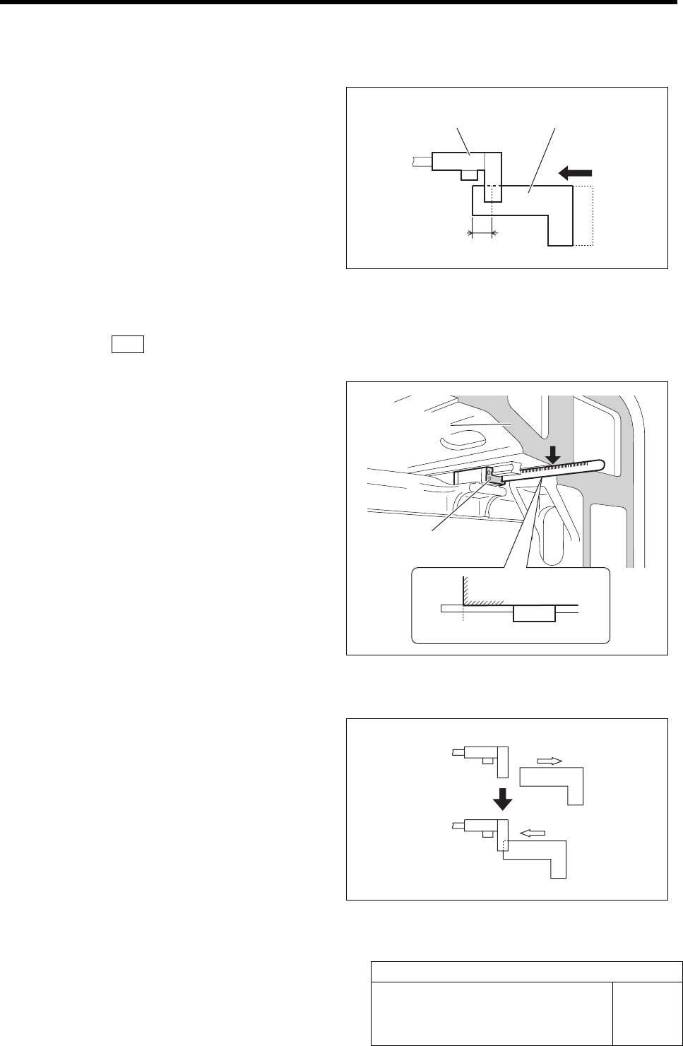
4 Stop the X axis at the boundary position
where the ORG sensor LED in extinguished
condition lights up.
1. Manually move the X axis in right di-
rection to the position where the dog
leaves the ORG sensor.
2. Manually move the X axis in left di-
rection little by little and stop at the
boundary position where the ORG
sensor LED in extinguished condition
lights up.
ORG sensor Dog
5 mm
A (122.5)
LM
Extinguished
Lights-up
Frame end face
LM guide face
Matching of X Axis Z-Phase
HLF-10401-01
Matching of X Axis Z-Phase
SHEET
2/3
5 Measure the dog detection position of the
ORG sensor.
1. Measure the distance from the frame
end face to the LM guide face on the
left side of the unit with a scale.
Suppose that the measured value is B.
(Example : 130.5 mm)
By 2 times of measurements, the amount of movements from the dog detection position of an
ORG sensor to the present Z-phase position can be found.
Suppose that the present amount of movement is C.
Example : A (122.5 mm) - B (130.5 mm) = C (-8 mm)
6 The difference between the present mount of movement and the amount of Z-phase set-up
movement “5 mm” is searched for. Suppose that this difference is D.
Example : Present amount of movement (-8 mm) + Amount of Z-phase movement (5 mm)=D (-3 mm)
Since the present amount of movements is too as large as -8 mm, the adjustment made small 3 mm is required of this example.
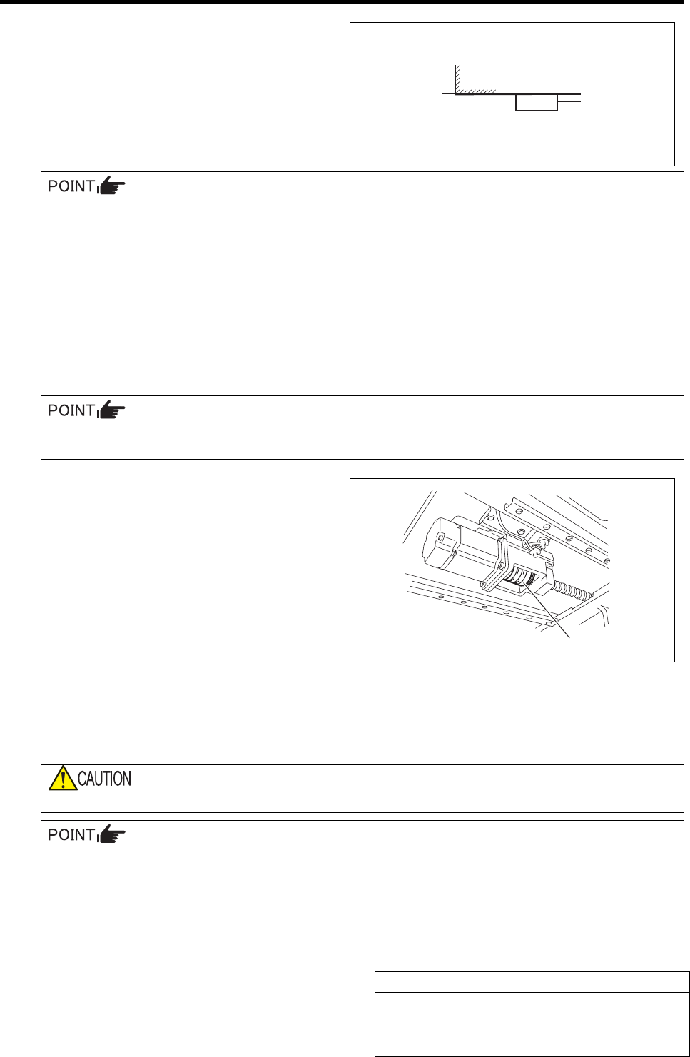
7 Adjust the Z-phase set-up position.
Adjust the Z-phase set-up position by adjusting the positional relation between the motor and
ball screw.
1. Move the head to the center of X axis
to secure working space to loosen the
coupling screws.
2. Loosen the screw M5 on the ball screw
side of the coupling.
3. Measure the distance from the frame
end face to the LM guide face with a
scale. (Example : 235 mm)
Suppose that this measured value is E.
E (235 mm) - D (-3 mm) = Target dimension (238 mm)
4. Move the X axis by dimension of the difference (D) with set-up movement found in the
procedure 6.
Example : Adjust the X axis so that the distance between the frame end face and the LM guide face is 238 mm.
When the X axis is moved, the coupling should not be moved.
If the difference between the present amount of movements and the amount of Z-phase set-up
movement is positive, move the X axis to the CCW sensor side (left direction), and if the dif-
ference is negative, move it to the CW sensor (right direction).
5. Fasten the screw M5 on the ball screw side of the coupling with a torque driver.
Tightening torque : 7N・m
B (130.5)
LM
Coupling

Matching of X Axis Z-Phase
HLF-10401-01
Matching of X Axis Z-Phase
SHEET
3/3
8 Turn the emergency stop switch in the arrow direction to release the emergency stop state.
9 Press the ORG button on the operation panel to perform origin position return.
10 Check the Z-phase set-up position.
1. Measure the distance from the frame end face to the LM guide face with a scale. Suppose
that this measured value is A.
2. Measure the dog detection position of the ORG sensor with a scale.
Suppose that the measured value is B.
Check that a relation is obtained as A (Z-phase set-up position) =B - 5 mm (Z-phase set-up movement amount)
Tolerance level : ±1 mm