SI-F130 Manual(EN)_jpg_ Rev1.pdf - 第138页
Nozzle Omission Detection Sensor P osition Adjustment HLF-10417-01 Nozzle Omission Detection Sensor Position Adjus tment SHEET 3/4 7. Set the “5. Power tuning target va lue” to “2000” and press the MODE button. Changes t…
Nozzle Omission Detection Sensor Position Adjustment
HLF-10417-01
Nozzle Omission Detection Sensor
Position Adjustment
SHEET
2/4
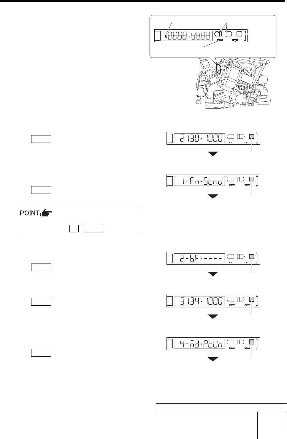
4 Set the nozzle omission detection sensor
amplifier mounted on the side of the head.
1. Turn the SET/RUN selector switch to
the “SET” side.
“Teaching” window appears, and present light
receiving value/threshold value are displayed.
2. On “Teaching” display, press the
MODE button to change the display
without doing anything.
Changes to the “1. Detecting function”.
3. Set the “1. Detecting function” to the
“Std (standard setting)” and press the
MODE button.
Changes to the “2. Timer function”.
To change the selecting items on each set
display, press the UP / DOWN button.
4. Set the “2. Timer function” to “------
(timer ineffective)” and press the
MODE button.
Changes to the “3. Display change” display.
5. On the “3. Display change”, press the
MODE button without doing anything.
Changes to the “4. MODE setting”.
6. Set the “4. MODE setting” to “(Power
tuning execution)” and press the
MODE button.
Changes to the “5. Power tuning target value”
display.
ON/OFF dis
p
la
y
p
art
MODE
button
SET/RUN selector switch
Operation mode
se
l
ecto
r
s
wi
tc
h
MODE button
MODE button
MODE button
MODE button
MODE button
UP/DOWN button
Nozzle Omission Detection Sensor Position Adjustment
HLF-10417-01
Nozzle Omission Detection Sensor
Position Adjustment
SHEET
3/4
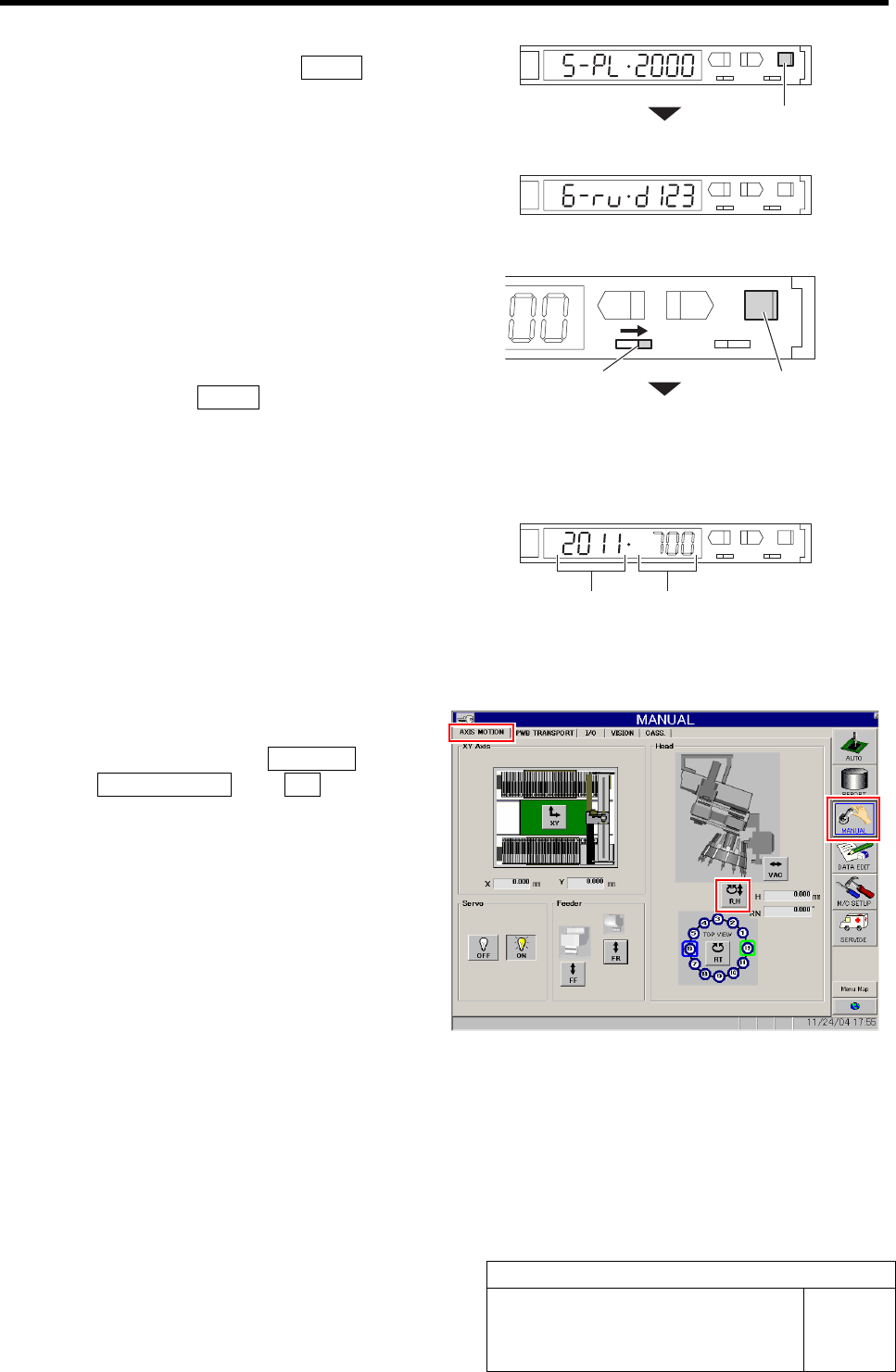
7. Set the “5. Power tuning target value”
to “2000” and press the MODE button.
Changes to the “6. Display direction”.
8. Set the “6. Display direction” to “D123
(normal setting)”.
5 Set sensitivity of the nozzle omission detec-
tion sensor.
1. Turn the SET/RUN selector switch to
the “RUN” side.
2. Press the MODE button for longer
than 3 seconds.
Light receiving value/threshold is automatically
adjusted.
L
SET RUN
UP DOWN MODE
D
3. Check the light receiving value.
If the light receiving value is within a range of
“2000±100”, setting is completed.
If the light receiving value is out of a range of
“2000±100”, re-perform the positional adjust-
ment of the nozzle omission detection sensor per-
formed in the procedures 2 and 3.
6 Set the threshold.
1. Click in an order of MANUAL menuÎ
AXIS MOTION tabÎR.H button.
RN/H Axis screen is displayed.
MODE button
SET/RUN selector switch
MODE button
Light receiving value
Threshold
Nozzle Omission Detection Sensor Position Adjustment
HLF-10417-01
Nozzle Omission Detection Sensor
Position Adjustment
SHEET
4/4
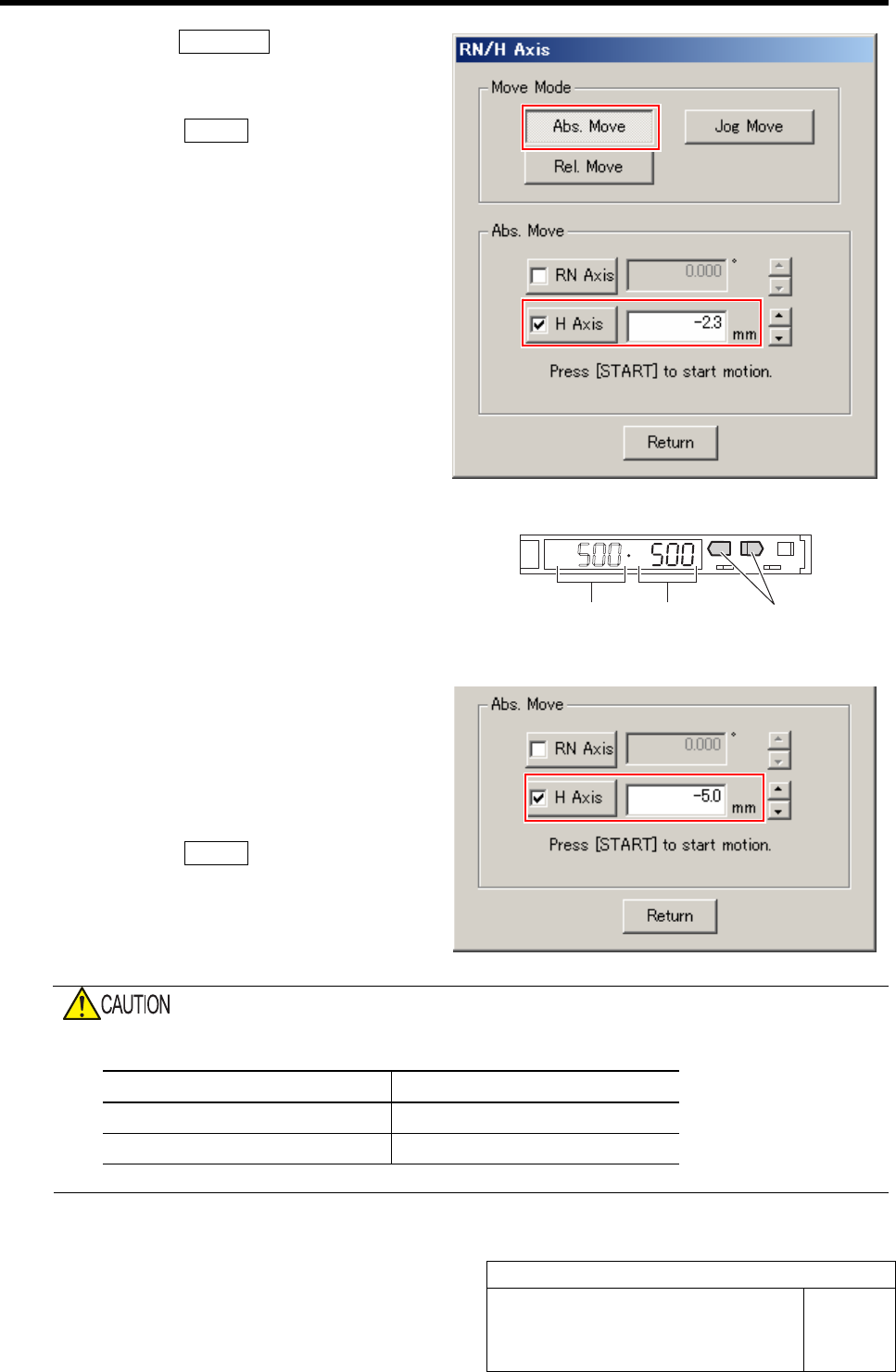
2. Click the Abs. Move button.
3. Click the check box for H axis and put
check in it to input “-2.3”.
4. Press the START button on the opera-
tion panel.
H axis lowers to a position of -2.3 mm.
5. Check the present light receiving
value with the nozzle omission detec-
tion sensor amplifier, and set its value
to the threshold.
Example: If the light receiving value is “500”, set
the threshold to”500”.
7 Check that the sensor is turned off at a posi-
tion where H axis is lowered by -5.0 mm.
1. On the RN/H Axis screen, click check
box for H axis and put check in it to
input “-5.0”.
2. Press the START button on the opera-
tion panel.
H axis lowers to a position of -5.0 mm.
3. Check that the sensor is turned off.
Do not confuse the lowering dimension when checking sensor OFF and the lowering dimension for
setting threshold.
Item H Axis lowering dimension
Threshold setting -2.3 mm
Sensor OFF check -5.0 mm
Light receiving value = Threshold
UP/DOWN button