SI-F130 Manual(EN)_jpg_ Rev1.pdf - 第164页
Blow Flow rate S etup HLF-10425-01 Blow Fl ow r ate Se tup SHEET 3/4 5 Install the flow rate measuring no zzle jig to the turret No.1. 6 T urn on the blow . 1. Click in an order of MANUAL menu Î AXIS MOTION tab Î VA C b …
Blow Flow rate Setup
HLF-10425-01
Blow Flow rate Setup
SHEET
2/4
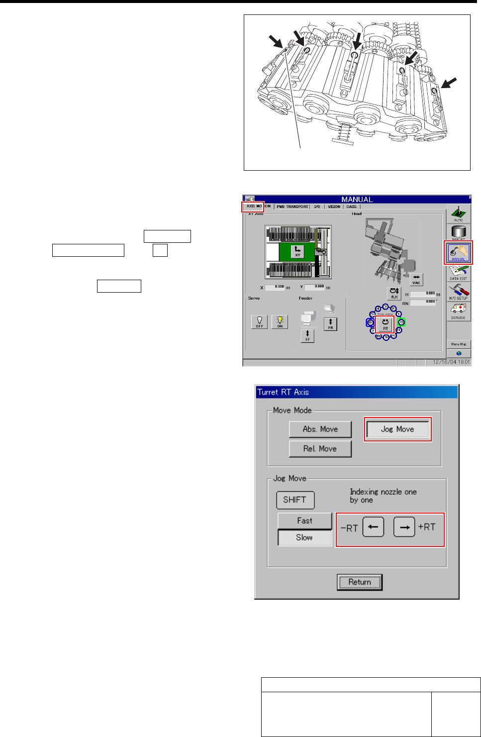
3 Push the upper part of the levers of the 12
mechanical valves on the head part to be
ready for blow-out.
4 Install the nozzle jigs (AF12080) to the tur-
rets No.2 to 12.
1. Click in an order of MANUAL menuÎ
AXIS MOTION tabÎXY button.
Turret RT Axis screen is displayed.
2. Click the Jog Move button in the move
mode.
3. Press the left and right cursor key to
rotate the turrets (No.2 to 12) to fit the
nozzle jig sequentially toward the
front, and install the nozzle jig.
Upper part of lever
Blow Flow rate Setup
HLF-10425-01
Blow Flow rate Setup
SHEET
3/4
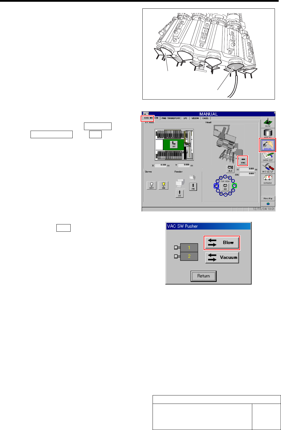
5 Install the flow rate measuring nozzle jig to
the turret No.1.
6 Turn on the blow.
1. Click in an order of MANUAL menuÎ
AXIS MOTION tabÎVA C button.
VAC SW Pusher screen is displayed.
2. Click the Blow button.
The blow is turned on.
3. Check that the value of the blow regu-
lator is “0.015 to 0.035 MPa” when in a
state of blow.
Flow rate measuring nozzle jig
Nozzle jig (AF12080)
Blow Flow rate Setup
HLF-10425-01
Blow Flow rate Setup
SHEET
4/4
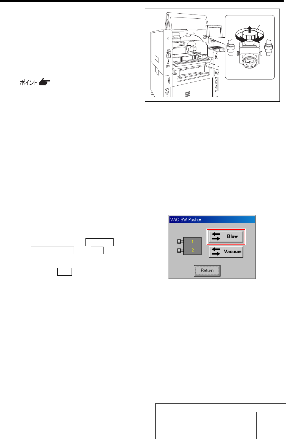
7 Turn the knob of the blow regulator to set the
measured value of the flowmeter to “0.28
L/min”.
1. Pull out the knob of the blow regulator
upward.
2. Turn the knob to adjust the air pres-
sure to “0.28 L/min”.
When adjusting the flow rate, make
measurement with the air tube being
straightened wherever possible.
3. Push in the knob downward and lock
the knob.
8 Check the blow flow rate of the turret No.2.
1. Remove the nozzle jig (AF12080) on the turret No.2.
2. Change the flow rate measuring nozzle jig on the turret No.1 onto the turret No.2.
3. Install the nozzle jig (AF12080) to the turret No.1.
4. Check that the measured value of the flowmeter is “0.20 L/min” or more.
5. Check that the value of the blow regulator is “0.015 to 0.035 MPa”.
9 Also check the blow flow rate of the turrets No.3 to 12 in the same procedure as in the procedure 8.
10 After adjusting blow flow rate, return the
blow back to OFF state.
1. Click in an order of MANUAL menuÎ
AXIS MOTION tabÎVA C button.
VAC SW Pusher screen is displayed.
2. Click the Blow button.
The blow is turned off.
11 Remove the flow rate measuring nozzle jig
and nozzle jigs (11 pieces) mounted on the
turrets.
Knob
Blow regulator