SI-F130 Manual(EN)_jpg_ Rev1.pdf - 第92页
Software Limit Setup HLF-10315-01 Soft w are Limit Setup SHEET 7/7 <S tandard table> Cassette No. Coordinate X Axis clearance Y Axis clearance Pickup position X Axis coordinate Y Axis coordinate Software limit 2 mm…
Software Limit Setup
HLF-10315-01
Software Limit Setup
SHEET
6/7
5 Determine the coordinate of the software
limit (SL) sensor.
1. Calculate the coordinate of the soft-
ware limit sensor on the X axis side to
meet the following conditions.
<Coordinate conditions>
- There is clearance of 2 mm or more from the
cassette pickup position.
- There is clearance of 1 mm or more to OT sen-
sor.
2. Calculate the coordinate of the soft-
ware limit sensor on the Y axis side to
meet the following conditions.
<Coordinate conditions>
- There is clearance of 1 mm or more from the
cassette pickup position.
- There is clearance of 0.5 mm or more to OT
sensor.
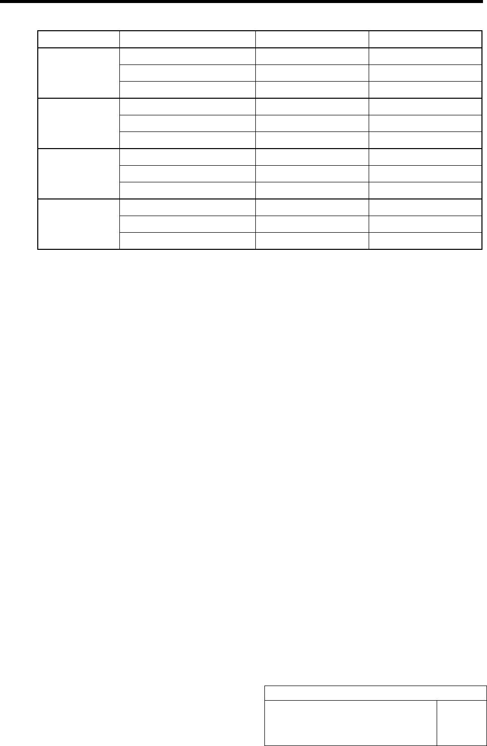
6 Set the software limit value.
1. Click in an order of M/C SETUP menu
ÎMOTOR PARAMETER tab
ÎAxis Param. tab.
Axis parameters screen is displayed.
2. Input the software limit coordinate
calculated in the procedure 5 into the
X, Y boxes on the software limit (+)
and (-) lines.
3. Click the Set button.
The set software limit values are saved.
7 Check the coordinates when the software limit is operating.
1. Click in an order of MANUAL menuÎAXIS MOTION tabÎXY button.
2. Click the Jog Move button on the XY Axis screen.
3. Press the cursor key to move the head in each direction of X-CW, X-CCW, Y-CW and Y-CCW
until software limit error is displayed.
4. Press the RESET button on the operation panel to cancel the alarm, and check that the XY
position displayed on the AXIS MOTION screen is within the standard in the next page.
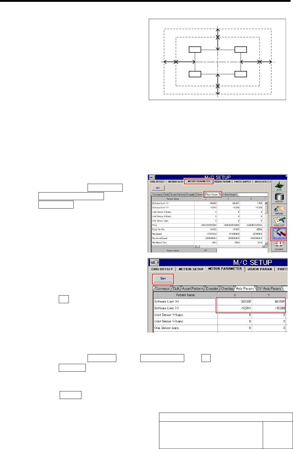
Nozzle operating area
OT boundary
Pickup position area
X-axis
Y-ax is
Z240
Z201
Z101
Z140
SL boundary
0.5 mm and more
1 mm and more
1 mm and more
0.5 mm and more
2 mm
and more
1 mm
and more
1 mm
and more
2 mm
and more
Software Limit Setup
HLF-10315-01
Software Limit Setup
SHEET
7/7
<Standard table>
Cassette No. Coordinate X Axis clearance Y Axis clearance
Pickup position X Axis coordinate Y Axis coordinate
Software limit 2 mm and more 1 mm and more
Z101
Over-travel 1 mm and more 0.5 mm and more
Pickup position X Axis coordinate Y Axis coordinate
Software limit 2 mm and more 1 mm and more
Z140
Over-travel 1 mm and more 0.5 mm and more
Pickup position X Axis coordinate Y Axis coordinate
Software limit 2 mm and more 1 mm and more
Z201
Over-travel 1 mm and more 0.5 mm and more
Pickup position X Axis coordinate Y Axis coordinate
Software limit 2 mm and more 1 mm and more
Z240
Over-travel 1 mm and more 0.5 mm and more
Conveyor Width Adjustment
HLF-10316-01
Conveyor Width Adjustment
SHEET
1/2
Conveyor Width Adjustment
[Necessary jig]
• Do not use jig.
[Procedure]
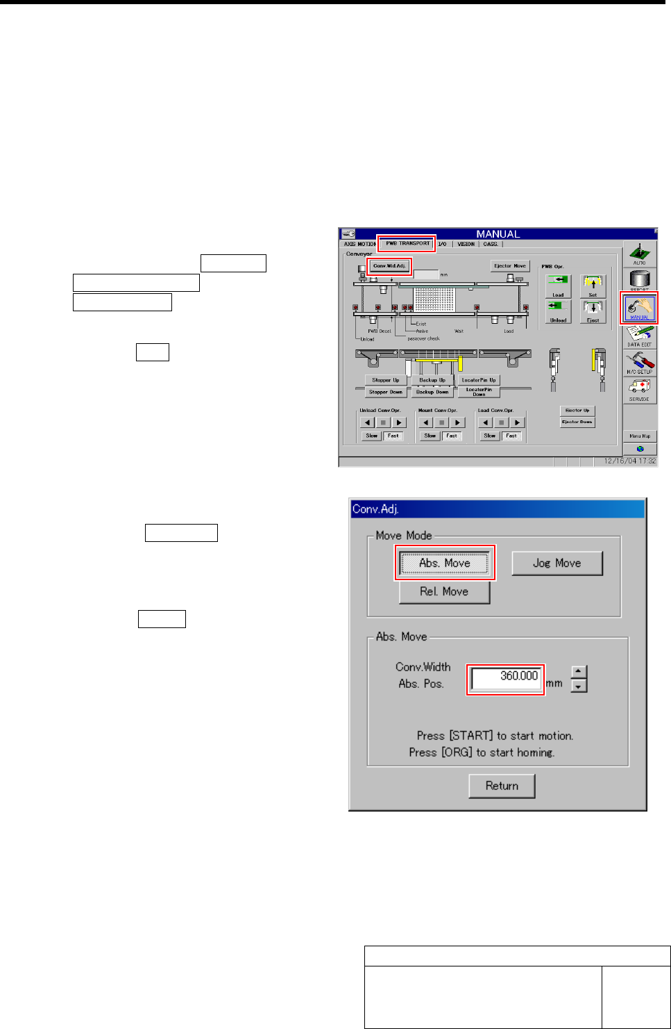
1 Perform origin position return of conveyor.
1. Click in an order of MANUAL menuÎ
PWB TRANSPORT tabÎ
Conv. Wid. Adj. button.
Conv. Adj. screen is displayed.
2. Press the ORG button on the operation
panel with the Conv. Adj. screen being
displayed.
Conveyor return to origin.
2 Set the conveyor width to 360 mm.
1. Click the Abs. Move button on the
Conv. Adj. screen.
2. Input “360” into the input box of the
Conv. Width Abs. Pos.
3. Press the START button on the opera-
tion panel.
Conveyor width is widened to the position of 360
mm.