SI-F130 Manual(EN)_jpg_ Rev1.pdf - 第115页
Adjustment of FF/FR Axis Belt T ension HLF-10407-01 Adjustment of FF/FR Ax is Belt T ension SHEET 3/3 7 Adjust the belt tension by turning the tension adjustment screw so that the maximum value of the tension measured in…
Adjustment of FF/FR Axis Belt Tension
HLF-10407-01
Adjustment of FF/FR Axis Belt
Tension
SHEET
2/3
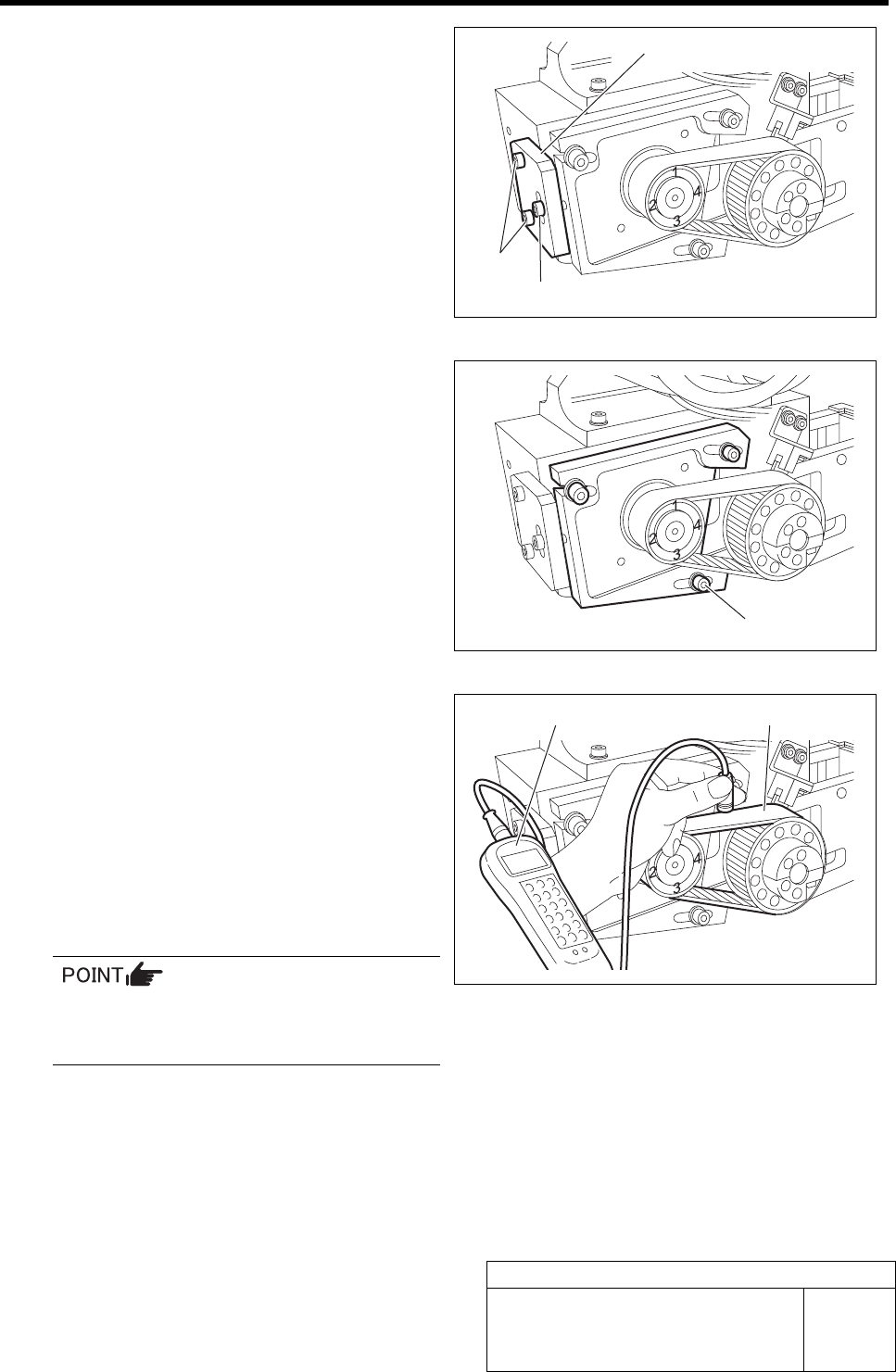
4 Install the tension block jig to the feed body.
5 Loosen the cap screws (3-M4) on the F axis
motor mounting bracket.
6 Measure the tension at positions of No.1 to
No.4 on the motor pulley in this order, and
check the position of maximum tension.
1. Set the measuring terminal of tension
meter near the belt on the middle be-
tween both pulleys.
2. When the belt is pulled by finger, ten-
sion value of the belt is displayed on
the tension meter.
For detailed operating method of the ten-
sion meter, refer to the manual attached to
the tension meter.
3. Measure the tension at positions of
No.1 to No.4 on the motor pulley re-
spectively, and check the position of
maximum tension.
Cap screw
Tension block jig
M4, W4
2-M3
Tension meter
Belt
Adjustment of FF/FR Axis Belt Tension
HLF-10407-01
Adjustment of FF/FR Axis Belt
Tension
SHEET
3/3
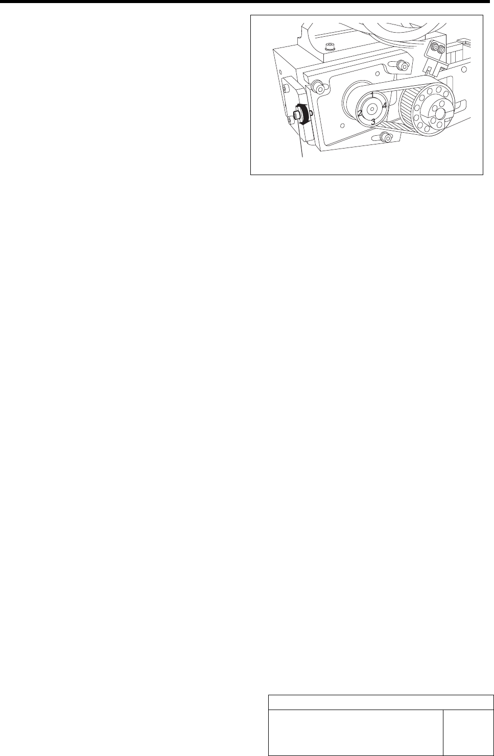
7 Adjust the belt tension by turning the tension
adjustment screw so that the maximum
value of the tension measured in the pro-
cedure 6 is within the standard.
Standard: 6 kgf < Maximum value < 7 kgf
(Target:6.8 kgf)
8 After adjusting the tension, retighten the cap screws (3-M4) on the F axis motor mounting bracket to
secure the bracket.
9 Remove the tension block jig.
Tension adjustment screw
Adjustment of FF/FR Axis Feed Roller Y-Direction Position
HLF-10408-01
Adjustment of FF/FR Axis Feed
Roller Y-Direction Position
SHEET
1/2
Adjustment of FF/FR Axis Feed Roller Y-Direction Position
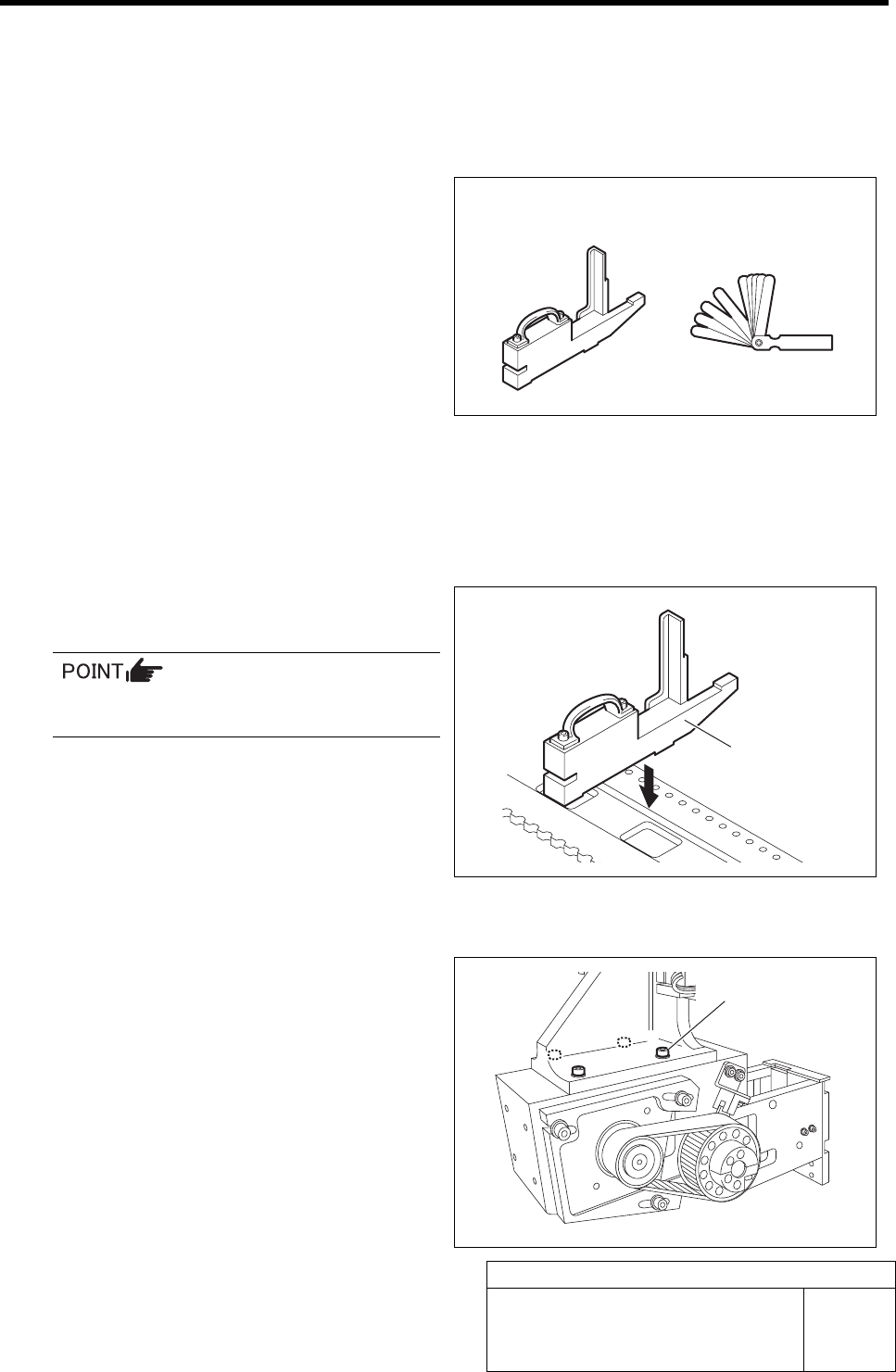
[Necessary jigs]
• Feed adjusting jig
• Thickness gauge
[Procedure]
1 Move the X axis to a position approximately
10 cm right from the position of No.20 on the
cassette table.
2 Set the feed adjusting jig to the No.20 posi-
tion on the cassette table.
There should be no gap between the feed
adjusting jig and the cassette table.
3 Move the X axis by hand to move the feed
body to the top of the feed adjusting jig.
4 Loosen the cap screws (4-M4) fastening the
feed body.
Feed adjusting jig Thickness gauge
Feed adjusting jig
Cap screw