SI-F130 Manual(EN)_jpg_ Rev1.pdf - 第17页
How to Display Cali bration Screen HLF-10103-01 How to Display Calibration Screen SHEET 3/3 When jig has b een selected, a CALIBRA TION screen appears. For machine setup and respective calibrations described in the follo…
How to Display Calibration Screen
HLF-10103-01
How to Display Calibration Screen
SHEET
2/3
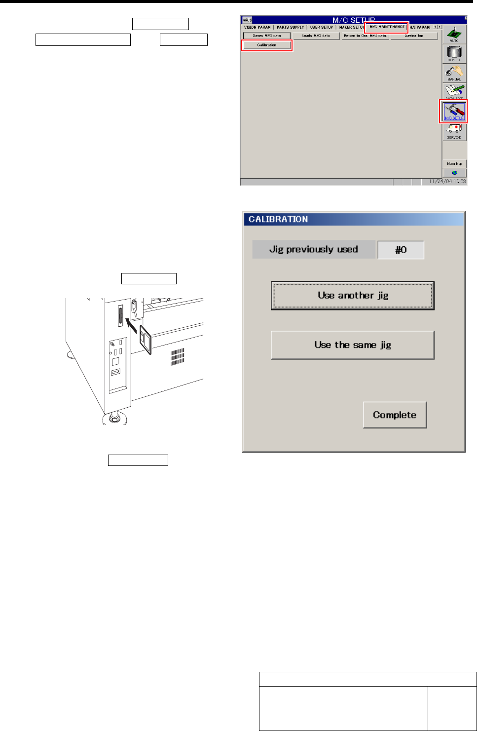
3 Click in an order of M/C SETUP menuÎ
M/C MAINTENANCE tabÎCalibration but-
ton.
A select screen for jig used for calibration appears.
4 Select jig used for calibration.
When performing calibration for the first time, or
when performing calibration by using jig different
from the previous one, set a floppy disk storing ma-
chine data and click the Use another jig.
If calibration has been previously performed by using
the same jig, click the Use the same jig.
How to Display Calibration Screen
HLF-10103-01
How to Display Calibration Screen
SHEET
3/3
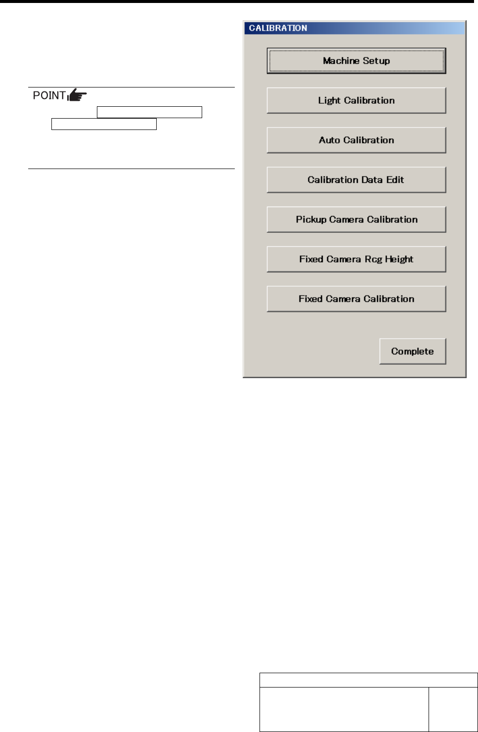
When jig has been selected, a CALIBRATION screen
appears.
For machine setup and respective calibrations described
in the following pages, the respective operation screens
can be opened from this menu.
Two buttons of Fixed Camera Rcg Height button
and Fixed Camera Calibration button do not be-
come effective unless all calibrations from Ma-
chine Setup to Pickup Camera Calibration are
correctly completed.
RT Axis Origin Position Setup
HLF-10201-01
RT Axis Origin Position Setup
SHEET
1/5
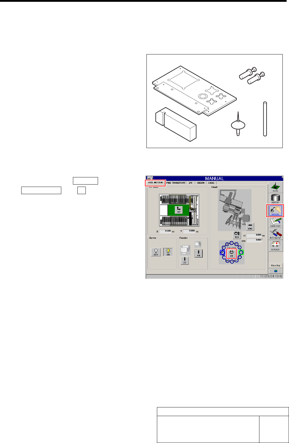
RT Axis Origin Position Setup
[Necessary jigs]
A Calibration plate jig
B Jig positioning pin
C Nozzle jig (AF06040)
D RT jig shaft
E RT jig block
[Procedure]
1 Click in an order of MANUAL menuÎ
AXIS MOTION tabÎRT button.
Turret RT Axis screen is displayed.
A
B
E
C D